First Build, getting no sound. Sandspur Fuzz

Verbzilla

New member
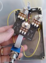
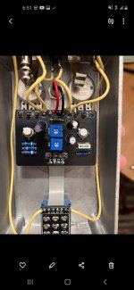
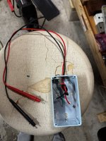
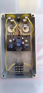
Does anyone see anything wrong from the photos? Pedal switches on with no sound. Bypass signal works fine and led comes on.

I think the transistor readings are way off. What would cause this?
Transistor readings with multimeter (volts)
Q1:
E 0, B.022, C.459

Q2:
E 0, B.459, C.442

Thanks for your help, I'm sure I must have screwed something up? Haha
 

Attachments

  • 20260927_131152.jpg
    20260927_131152.jpg
    199.4 KB · Views: 66
  • 20260927_165927.jpg
    20260927_165927.jpg
    227.6 KB · Views: 66
A few things to try - the tip lug on the output jack may need the connection run through the eyelet and re-soldered. Also re-flow all solder connections and closely trim all leads. Look for possible solder bridges (looks like possible bridge between SW and out on the stomp switch daughter board).
 
Thanks everyone for the helpful tips and suggestions! I am getting 9v on each side of the diode. Also with the sundial at noon, I'm only able to get a range of 1.1v - 2v on the collecter of Q2. They're bc108's from Stompbox.

This week I will make sure to reflow all connections again and clip all the leads a little more. I will inspect everything again as well.
 
Thanks guys! The 5 band colors on R2 look to be: orange, orange, black, red, brown. Is that 33k or 330k?
It's much easier if you get a cheap DMM and take a reading of the actual resistance. Not only does that prevent using the wrong value, but also would prevent using a component this is not up to spec. I don't bother with reading any color bands anymore, I measure the resistance of every resistor (and measure capacitors too). It's fast and I'm sure.
 
Well darn.. When I first looked at them it all looked correct... but the R2 did look like orange orange black orange brown... looking closer it does look darker than orange... so looks like your components are right...
 
It's much easier if you get a cheap DMM and take a reading of the actual resistance. Not only does that prevent using the wrong value, but also would prevent using a component this is not up to spec. I don't bother with reading any color bands anymore, I measure the resistance of every resistor (and measure capacitors too). It's fast and I'm sure.
This is  my way (too).

If you get an LCR meter you can check capacitors too. Some DMMs also check capacitance but in the pF range I trust my LCR over my fairly expensive Fluke 87V DMM (which is intended more for large caps as found on single phase motors).
 
I did not test any of the resistors or capacitors prior to installing. Would it be beneficial to de solder and re solder all of those specific components with verified new ones? Trying to find guidance for my next steps.. I will also re flow all of the existing solder points as well.

Anyone have a link to a cheap LCR Meter to test capacitors with? I have a DMM already.
 
probably the best thing to do from here is make yourself an audio probe.... watch some videos... can be made using a 100n capacitor and a guitar cable in it's simplest form..... I ended up making mine out of a misdrilled enclosure, 1/4 audio jack and a couple multimeter leads...
 
I purchased a cheap LCR meter & I will make sure to measure resistors & capacitors before hand for future builds.

I also am going to grab a 100n capacitor to make an audio probe. Pretty cool how this works! Hoping this will give me an answer to my no sound issue.

Thanks everyone for your help. Once I get stuff in the mail I will get to work on the audio probe stuff.
 
Back
Top