
caiofilipini
Well-known member
Hey all,
I'm building a 2-in-1 overdrive pedal, a Mach 1 on the right side and a Pauper on the left side. I wired everything according to this diagram:
 wiki.pedalpcb.com
The only difference is I'm using the 3PDT breakout boards, but AFAICT it should be pretty much the same, as long as the output of the first breakout board is connected to the input to the next board, which is what I did. Also, due to space constraints, I used a 4-pin header to connect the Pauper's breakout board to the main board.
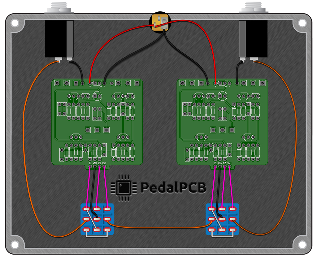
Here's my build:

The Mach 1 (PCB on the left-hand side of the picture) works when engaged, but the Pauper doesn't. Bypass signal works fine, which tells me the jacks are wired correctly. I also checked for voltages on the op amp and all diodes in the Pauper, as well as continuity between all offboard connection points, and also between the pin header and the 3PDT breakout board, and everything looks good AFAICT.
Did I overlook anything obvious in the wiring diagram? Any other obvious places I should check next? Also happy to provide more detailed pictures if it helps.
Appreciate the help, folks!
I'm building a 2-in-1 overdrive pedal, a Mach 1 on the right side and a Pauper on the left side. I wired everything according to this diagram:
2-in-1 Pedal Wiring - PedalPCB Wiki
The only difference is I'm using the 3PDT breakout boards, but AFAICT it should be pretty much the same, as long as the output of the first breakout board is connected to the input to the next board, which is what I did. Also, due to space constraints, I used a 4-pin header to connect the Pauper's breakout board to the main board.
Here's my build:
The Mach 1 (PCB on the left-hand side of the picture) works when engaged, but the Pauper doesn't. Bypass signal works fine, which tells me the jacks are wired correctly. I also checked for voltages on the op amp and all diodes in the Pauper, as well as continuity between all offboard connection points, and also between the pin header and the 3PDT breakout board, and everything looks good AFAICT.
Did I overlook anything obvious in the wiring diagram? Any other obvious places I should check next? Also happy to provide more detailed pictures if it helps.
Appreciate the help, folks!