3pdt different types of wiring

kingbarnes

New member
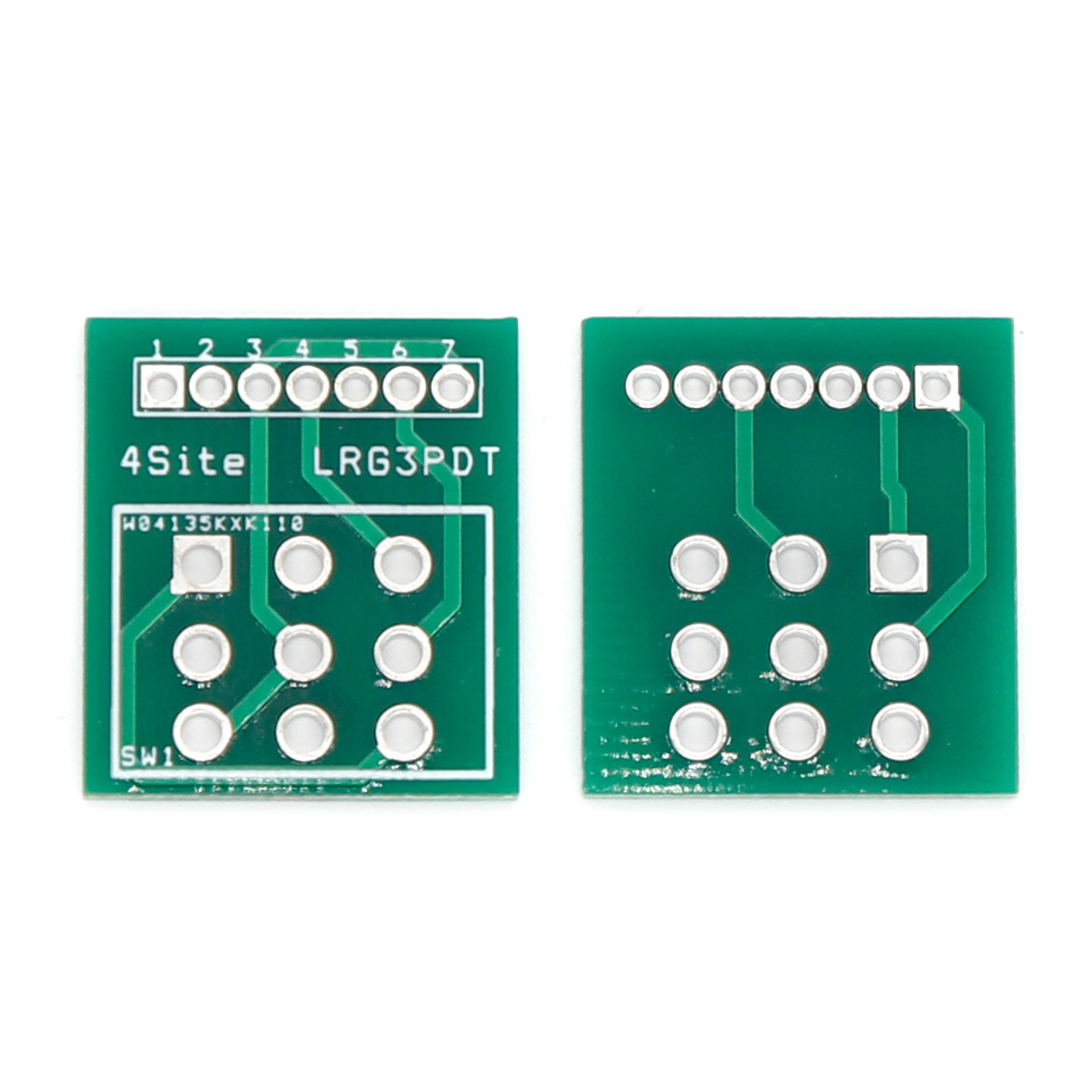
I'm seeing that there are different types of 3PDT switches, meaning there is different wiring!!! I'm seeing a 3PDT PCB from stompboxparts.com that has wiring that only matches some types of footswitches but not others, and the usual template from PedalPCB.com:

1680099344326.png

And this shows wiring that is completely different. It also mentions some switches are compatible and some are not.


_MG_5168__66911.1587743684.jpg


I had a thread about my Underminer sub-octave pedal having no sound when the footswitch was engaged. I built a second one and same thing. There were no issues that I could find, but now i'm thinking i have footswitches that should be wired differently than what I've usually done, which is what's shown above from pedalpcb.com (which i had 2 previous successful pedals but those had different 3PDT switches than what i used in the 2 Underminer pedal builds).

So I'm thinking it's worth tyring to put the 3PDT on a board from stompboxparts.com, wire that, and see if my pedal builds then work. It does make sense to me that this could be the cause.

Thoughts?
 
The 3PDT footswitches themselves all function the same way (with the exception of latching vs momentary).

Any compatibility issues between a footswitch and breakout board would be physical dimensions, not electrical functionality.

Most breakout boards are doing the same thing, they're just laid out slightly differently. The main difference is that some will ground the PCB input in bypass to reduce noise but this won't affect normal operation.

Where you have to be careful is matching the pinout of the breakout board to the effect PCB you're pairing it with.


If you used the PedalPCB breakout board you shouldn't have any issues, regardless of where you got your 3PDT footswitch from. These line up pin-for-pin with most of the true-bypass PCBs here (including the Underminer) .. If you use a breakout board from another vendor you'll have to check their documentation to see the pinout used.

If you're concerned that the breakout board is the issue you can just wire the footswitch up like the image in your post.
 
Thank you, but not at all what I was hoping to hear. According to the board at stompboxparts.com, they are bridging different pins than I have been doing. My pic here doesn't do justice, but here it is anyway:

PXL_20230317_220938285.jpg


In that wiring, I have pins 1 and 8 bridged, and 7 & 9 bridged (per the pedalpcb.com picture in OP), the pins 4 & 6 connected to IN/OUT jacks, and the rest connect to the main pcb. In the shots above from the 3pdt pcb from stompboxparts.com, they are bridging pins 1 & 9 and 5 & 7, which is completely different, so that doesn't back up what you're telling me. BUT that makes sense in the fact that the board above (giant picture of green board) has this listed:

"Fits 3PDT's sku 800-1017 and 800-1028.
Does NOT fit 3PDT sku 800-1032 or low profile 3PDTs."

So that may just be the physical size of the switches, but why then is there different bridging of pins? That's what I'm not understanding.
 
If you used the PedalPCB breakout board you shouldn't have any issues, regardless of where you got your 3PDT footswitch from. These line up pin-for-pin with most of the true-bypass PCBs here (including the Underminer) .. If you use a breakout board from another vendor you'll have to check their documentation to see the pinout used.

If you're concerned that the breakout board is the issue you can just wire the footswitch up like the image in your post.
How those of us who wire switches look at those who use breakout boards 😂
Screenshot_20230328-154604.png
 
So that may just be the physical size of the switches, but why then is there different bridging of pins? That's what I'm not understanding.

A 3PDT footswitch is three independent dual throw switches. Different breakout boards might be arranged slightly differently but they're achieving the same end result.

Where the PedalPCB breakout board (and wiring diagram) might use the outer columns for switching the audio path and the center column for switching the LED, others might use the two left columns for the signal path and the right column for the LED. (or the inverse)

There are several variations but for the most part they behave the same.
 
Ok, thank you, that sort of makes sense to me. I've always wired the 3pdt manually, never used a breakout board, so I didn't know some were wired differently (but acheived the same result).
 
Yes, mine is rotated 90° in the picture. Sorry for wrong pin numbers but thank you for this diagram! I'm at work and that was only photo I had on my cell to include here.
 
Yes, mine is rotated 90° in the picture. Sorry for wrong pin numbers but thank you for this diagram! I'm at work and that was only photo I had on my cell to include here.
No, I mean I think you've wired it up with everything rotated 90º. That won't work. They are symmetrical 180º, but not with 90º rotation. If that's the case, you'll need to rewire the switch.
 
Are you telling me I wired it correctly but with the switch itself rotated? Holy cow! With the bypass sound working correctly and the LED switching ON/OFF correctly, I never even considered that!
 
Are you telling me I wired it correctly but with the switch itself rotated? Holy cow! With the bypass sound working correctly and the LED switching ON/OFF correctly, I never even considered that!
Again, I can’t tell from your image and your pin naming is confusing. That could be the case.

You can take the switch out of the equation and short the input jack to IN and output jack to OUT to see if the board passes signal. There are a lot of variables here. Clear pictures would be very helpful.
 
Back
Top