3PDT or 4PDT for "mod" switch, on-on toggle

maertz13

Member
hi folks, i'm relatively new here, so if there's already a thread on this that comes mind, i'd appreciate a link.

i'm looking into building a klon, but making some tweaks with popular mods. a toggle for clipping diodes, a toggle for a fat switch, and the one i need help with, a switch to change the value of 3 resistors in the chain. i've read as many things as i can find on switches, and i haven't quite found the answer for this. is it even possible?

thanks
 
If you want to change three components all at once, then you want a 3PDT.

3 poles, double throw.
Diagram 5 shows the mapping.

The center lugs are the poles, this will be whatever is common for both throws. The you connect the components you want to switch between on the corresponding throws.
 
I think of the poles as the vertical columns in a switch.

To avoid some confusion, I like to name the poles rather than number them like the lugs — just something I've seen other people do...

SPDT Pole A includes lugs 1,2,3
DPDT Pole B lugs 4,5,6
3PDT Pole C 7,8,9
4PDT D 10, 11, 12


So a 3PDT c'est comme ca with the lugs horizontal:

POLE APOLE BPOLE C
LUG #1 —4 —7 —
LUG #2 —5 —8 —
LUG #3 —6 —9 —

Centre-Lugs 2, 5, and 8 are the common lugs respective to their pole and lugs on either side within their pole.
 
so i follow the part where i can tell 3 incoming signals wired to common to go either one side or the other, but i'm not entirely sure how i'd do that with resistors. 2-5-8 from the board, the "stock" stock resistors on 1-4-7 to the board, and the "mod" resistors on 3-5-8 to the board. but won't that load down the circuit? or am i overthinking this?
 
so i follow the part where i can tell 3 incoming signals wired to common to go either one side or the other, but i'm not entirely sure how i'd do that with resistors. 2-5-8 from the board, the "stock" stock resistors on 1-4-7 to the board, and the "mod" resistors on 3-5-8 to the board. but won't that load down the circuit? or am i overthinking this?
You're adding a switch before or after two otherwise parallel resistors.
One side is a common node, the other side is the switch.
You either break the path to or from them individually.
Common deployment would be Rx pad 1 to center lug(well say lug 2). Resistors tied to lugs 1 and 3, then they share a node(tied together) at the other legs with a wire that return to the other resistor pad(Rx pad 2).
Repeat for Ry and Rz.
You could do it neater with a 3pdt breakout board I think but I can't find the one that had pads for this.
You're switching the path to the resistor though. One resistor will always be dangling between the common node and a non connect switch pad.
Hope that helps.
 
Note, the common node can also be on the pcb, or on a piece of protoboard, whatever fits better and is easier for you.
Another option is switching in series and parallel resistors, which would be better because you'll never have an open circuit, but that's a longer post.
 
so i follow the part where i can tell 3 incoming signals wired to common to go either one side or the other, but i'm not entirely sure how i'd do that with resistors. 2-5-8 from the board, the "stock" stock resistors on 1-4-7 to the board, and the "mod" resistors on 3-5-8 to the board. but won't that load down the circuit? or am i overthinking this?

It won't load it down, not by any significant measure. Electricity doesn't like dead-ends, which is what it'll find trying to flow up the side of the switch that isn't in play.

From the "circuit's perspective", it will be as if you've soldered in the stock values, or soldered in the mod values — it doesn't "see" the unused values on the other side of switch that aren't being used.

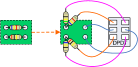
Maybe these Beavis diagrams will help:

images

So, you'll be using the lower SPDT diagram;
Here's a DPDT, basically two SPDTs stuck together ...

Switch2sets.gif


... but you'll have three SPDTs in one switch — a 3PDT.


Something that may also interest you:
AH, so i AM overthinking it. thank you for clearing that up. my fear was that since resistors have no polarity, that it would still be in play. my understanding was the the only thing that will stop electricity from going backward was a diode.

EDIT: i just realized i was thinking about it backwards. i was putting the switch first and telling it which resistor to choose, not sending it down both resistors and then only letting one pass at a time. way better :D
 
Last edited:
AH, so i AM overthinking it. thank you for clearing that up. my fear was that since resistors have no polarity, that it would still be in play. my understanding was the the only thing that will stop electricity from going backward was a diode.

EDIT: i just realized i was thinking about it backwards. i was putting the switch first and telling it which resistor to choose, not sending it down both resistors and then only letting one pass at a time. way better :D

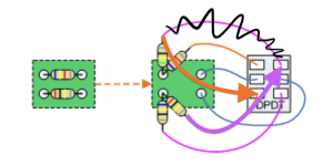
I just noticed an error in Beavis' DPDT diagram. The resistor paths are crossed up!

In Beavis' example resistor "A" and its alternate go to different poles, as does resistor B respectively — so when swapped out you're now sending resistor A along path B and vice versa. Incorrect! See what I mean?

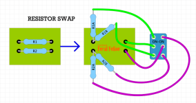
To truly swap between two different values, A has to have its own pole as should B:

BEAVIS CORRECTION.png


Here's a cleaned up version without paths crossing:

RESISTOR-SWAP SWITCH 2023-06-20 (BEAVIS CORRECTION).png

If the signal path is from left to right, then note above how the resistors are fed signal, sending it to the switch which then passes on the signal to the return. For an unfathomable reason, I don't like this.


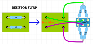
I prefer to send the raw signal to the switch which then sends it to one component (set) or another and have the signal return to the PCB via whichever component the switch has selected:


RESISTOR-SWAP SWITCH  2023-06-20 FFFX.png


Electricity doesn't care which way you do it, but I prefer my way, it just seems more logical to me somehow, cleaner.
 
Back
Top