9V protections for projects with a voltage doubler (muzzle, klon...)

Paul.Ruby

Active member
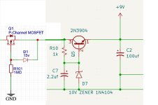
I just saw a post over on the gear page about folks blowing up their KTR by applying 18V accidentally. IMO, pedal makers should expect such a thing to happen and handle it gracefully. The common voltage doubler chips have a max operating voltage of 10V. Pedals that use them usually have a zener diode to shunt away the high voltage. But, those burn up and don't really provide any protection. They will either short or open, both of which is fatal to the pedal. I've added this to my muzzle builds to keep the voltage under about 9.6V, even if the input is 18V. This came in handy for my combo-build that has a muzzle but also includes other modules that I prefer to have 15V. Dirt simple linear regulator. 1714419145263.png
 
Last edited:
That's a nice and elegant approach. On any of my builds that use voltage-sensitive components like a LT1054 or certain germanium transistors, I use include this circuit, which handles reverse polarity protection and over-voltage protection. And as a bonus, it has almost no current draw or voltage drop.

1714419962632.png
 
IMO, pedal makers should expect such a thing to happen and handle it gracefully
I'm inclined to ask, should your vehicle's manufacturer expect you to fill your gasoline car with diesel? Would your gasoline car handle it gracefully?

Even in a well-regulated industry, such as the automobile industry, manufacturers don't do everything to protect against all forms of user-error.

Don't get me wrong, I commend a pedal manufacturer that goes the extra mile to prevent mishaps, but I won't fault one for not protecting me against my own mistakes.
 
Last edited:
I'm inclined to ask, should your vehicle's manufacturer expect you to fill you gasoline car with diesel? Would your gasoline car handle it gracefully?

Even in a well-regulated industry, such as the automobile industry, manufacturers don't do everything to protect against all forms of user-error.

Don't get me wrong, I commend a pedal manufacturer that goes the extra mile to prevent mishaps, but I won't fault one for not protecting me against my own mistakes.
It's not an extra mile. It's an extra inch.
 
With modern power supplies, it's gotten very easy to accidentally feed well over 9 volts into your pedals. Take the popular Cioks power supplies, for example. They use a slightly recessed pair dip switches on the top of the device to set the voltage for each tap. It's not too difficult to accidentally switch the dip switches from 9 volts to 18 volts, or even confuse the 9 volt and 18 volt settings, as some of their supplies don't include a legend on top:
cioks4.jpeg
I've also seen increasing number of pedals that run at 18 volts. All it takes is forgetting or mistaking which of the tangle of DC cables is the 18 volt cable, and *poof* you've killed a pedal. If anything, I think that you're more likely today to kill a non-battery pedal with over-voltage than reverse polarity—I haven't encountered a 2.1mm center positive supply for years. I'd skip the over-voltage protection it on something where the lowest rated component is a 35 volt cap, but otherwise I think it's worth including.
 
Last edited:
It's not an extra mile. It's an extra inch.
I'd skip the over-voltage protection it on something where the lowest rated component is a 35 volt cap, but otherwise I think it's worth including.
I'm not saying that manufacturers shouldn't include user-error protection, in fact, I believe I said that I commend those that do. My point was that some of the onus falls on the end-user and regardless of how over-engineered a product is, someone will find a way to break it.
 
With modern power supplies, it's gotten very easy to accidentally feed well over 9 volts into your pedals. Take the popular Cioks power supplies, for example. They use a slightly recessed pair dip switches on the top of the device to set the voltage for each tap. It's not too difficult to accidentally switch the dip switches from 9 volts to 18 volts, or even confuse the 9 volt and 18 volt settings, as some of their supplies don't include a legend on top:
View attachment 74068
I've also seen increasing number of pedals that run at 18 volts. All it takes is forgetting or mistaking which of the tangle of DC cables is the 18 volt cable, and *poof* you've killed a pedal. If anything, I think that you're more likely today to kill a non-battery pedal with over-voltage than reverse polarity—I haven't encountered a 2.1mm center positive supply for years. I'd skip the over-voltage protection it on something where the lowest rated component is a 35 volt cap, but otherwise I think it's worth including.
Exactly. Three questions during engineering: How easy is it to see an overvoltage? How risky is an overvoltage? How much does it cost to eliminate the risk? It's trivially easy to make the mistake. Catastrophic to some designs (those with voltage doublers and only zener protection). Trivially easy (inexpensive) to eliminate the risk. No brainer for me.
 
I'm not saying that manufacturers shouldn't include user-error protection, in fact, I believe I said that I commend those that do. My point was that some of the onus falls on the end-user and regardless of how over-engineered a product is, someone will find a way to break it.
I agree with you that the end user is ultimately responsible for taking care of their pedal, and that if they fry the pedal by using the wrong power supply, it’s 100% on them. At the same time, I think builders should consider mitigating risks like users connecting the wrong power supplies, and reevaluate as the risks and costs of mitigation change. A very similar debate to the one that we're having here played out a couple decades ago regarding series diode protection, which is now commonplace and noncontroversial. I think that the increased use of PCBs helped settle that debate by making it extremely cheap and easy to add a protection diode. I suspect that the same may happen with over-voltage protection along with the wider adoption of SMD assembly (through-hole P-channel Mosfets are too expensive and require too much space to justify an over-voltage protection circuit). The circuit in my earlier post costs ~50 cents and takes up about the same space as a 100u cap if it’s all done via SMD.
 
Last edited:
My circuit costs ~50 cents and takes up about the same space as a 100u cap if it’s all done via SMD.
Are you just changing D102 based on max voltage your circuit can accept? Your design should be less lossy than the design @Paul.Ruby posted. Have you measured losses and what are the current capabilities of this protection scheme (if you are willing to share)?
 
Are you just changing D102 based on max voltage your circuit can accept? Your design should be less lossy than the design @Paul.Ruby posted. Have you measured losses and what are the current capabilities of this protection scheme (if you are willing to share)?
Correct, D102 helps set the cutoff voltage, which is ~1.5v above the diode's zener voltage (precisely how far above the zener voltage is dependent on the VGS(threshold) of the mosfets that you are using). So using an 8.2v zener for D102 would set the cutoff voltage at 9.8v, and a 9.1v zener would cutoff voltage at 10.6v. Nothing that I use has a maximum voltage rating of less than 12v, so I use a 9.1v zener to allow for the use of 9v supplies with a high output (quite a few 9v supplies output as much as 9.7v).

The voltage drop depends on the RDS(on) value of the Mosfets. Lower values of RDS(on) consume less current and drop less voltage. I used CJ3407-ES mosfets in a recent order, and they have an RDS(on) that's ~60mΩ at 10v. When used with a 9.27v power supply, the voltage drop is less than 0.01v. The current consumption is so low that I can't measure it. It can handle a lot of current; the limiting factor is the mosfet rating, which is typically at least a couple of amps.

The other important parameters to consider when selecting mosfets are the maximum VDS and VGS ratings. You'll need a device VDS and VGS(max) that is higher than any voltage that you would expect the pedal to ever see. Most mosfets now have a VDS(max) of at least 30v, which is plenty for our purposes. It's likewise easy to find mosfets with a VGS(max) of 20v, which is enough to protect a pedal from an 18v power supply.

If you're interested, I've made a Circuit Lab simulation of the circuit that you can experiment with here.
 
Last edited:
@PedalBuilder and @Paul.Ruby -
Those are quite elegant solutions!

Hmm, but @Brett's fuel analogy suggests another approach, akin to using a different size fuel nozzle and fuel inlet.
I.e., use a different power connectors for stompboxes that can vs can't accept 18V, w/ mating connectors on 9V only vs 9V/18V supplies.
For those of us that build our own, it might work.
Just a thought...
 
I like both @PedalBuilder’s approach and @Paul.Ruby’s shared design. This whole over-voltage thing is a non-issue for me, at least personally. The only 18V tap I have on my PSU runs to my tuner so there’s no surprises. All other adjustable taps are set to 9V. I’d love to say that I notice a difference between 9v and 18v, but it’s been pretty subtle in most cases (for me anyways).
 
Awesome stuff sharing the love! I would say that this is indeed trivial if you're making a layout for IO.
As much as we would love to blame the operator, we have all made dumb mistakes (now try doing it in the dark on stage!) and something simple like this can make a vastly superior consumer (and seller) experience.
 
Back
Top