A Regulated Isolated 9vdc Power Supply Layout

djmiyta

Well-known member
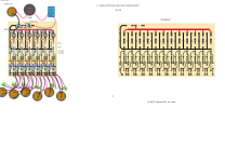
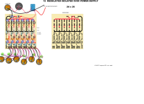
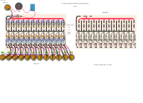
Hoping some one with more experience , expertise , and knowledge will take a look at my layout. See if anyone can spot anything wrong or something needs added or removed. Or even general criticism. I'm thinking its good to go and have been refining the layout for a week or 2 and feel pretty confident about it. This, according to AI, should rival and compare to the higher end of power supplies. each outlet has 222mA should be plenty of head room for almost all my pedal running at 9vdc. If this layout does work as expected then I'll make another for 12 and 18 volt pedals.

Thanks for your time in advance, it is very much appreciated.

Oh and the PCB board is powered by a 12vdc 5 amp power brick. I purchased new just for this project. Hoping I have no issues with that cause it came from TEMU or AliExpress
 

Attachments

  • NEW REGULATED ISOLATED 9VDC SUPPLY.png
    NEW REGULATED ISOLATED 9VDC SUPPLY.png
    1.2 MB · Views: 48
First, I don't have lot of knowledge but here are my thoughts, some might prove I know nothing of confirm ...

1 - Is that diode in the right way ?
2 - Is the top part only a simplified version with no led ? Not sure why the bottom parts only look like redundant ...
3 - How does AI comes with the 222mA
4 - What is the purpose of having 12 LEDs that are all always on ?
 
Looks fully isolated. As in, the top portion of the circuit is fully isolated from the bottom portion of the circuit.

I saw that too, I'm guessing the IB1209S called out in text makes up the "bridge" between the top and bottom portions. A quick web search said that is a DC-DC isolation device.

To @djmiyta, sounds like you already bought the 12v power supply. But you might consider adding a 5v USB-C power input, along with a boost converter (5v -> 12v) so you could optionally run it off the portable power banks that are readily available. Of course you can get a power bank in just about any voltage, but the 5v ones with USB-C are super common.
 
First, I don't have lot of knowledge but here are my thoughts, some might prove I know nothing of confirm ...

1 - Is that diode in the right way ?
2 - Is the top part only a simplified version with no led ? Not sure why the bottom parts only look like redundant ...
3 - How does AI comes with the 222mA
4 - What is the purpose of having 12 LEDs that are all always on ?
I can answer those for you:

1 - no it is not. The polarity protection diode is in fact blocking the correct polarity voltage from powering the circuit.
2 - top part is input filtering before each regulator, bottom part is output filtering after each regulator
3 - 2W of power at 9V = 222mA per output
4 - since these are isolated outputs, the LED is on as long as that regulator is functioning, it's a status LED for each output.

Aside from the backwards polarity protection diode I don't see anything inherently wrong with the design, but I also don't see anything that "rivals and compares to higher end power supplies" like Cioks or 1Spot Pro. Both of those are higher total output power as well as higher current per tap, allowing for powering things like the hungry digital pedals and tube pedals. Isolated is cool, 12 taps is cool, but 222mA is not considered a high current output these days.
 
The Mornsun A...S-2WR3 & B...S-2WR3 series have unregulated DC outputs according to the datasheet.
I missed that one when I was looking through, good catch. "Suitable when the requirement for a tight output regulation is not as strict."

So when whatever AI tool helped design this said it would rival higher end power supplies, it was just typical baseless AI flattery. Will the supply work (once you flip the diode around)? I absolutely expect that it will. Will it rival a high-end power supply? No it will not. Low current, unregulated, and assuming whatever AC/DC 12V supply it's fed from is going to be "clean enough" is not the way high-end supplies are designed.
 
Back
Top