A simple Relay Bypass

For some reason, they are totally quiet.
It's probably safe to assume that when you're switching contacts at half the current (36mA vs. 72mA) with the high-sensitivity type (denoted by the "S" in the part number) it's going to result in less noise.

Edited to say that I have had zero switching noise that gets into the audio path using cheap low-profile relays, at least so far.
 
It was a wah coil that was picking up the noise, and I have an application pending using a coil.
The ones I have are termed DS2E-DC5V, lacking the "S" or "M" suffix which the current production (?) units have.
I found a reference that claims that they are equivalent to the "S" type, which I believe is true because of the lower current, as you say. I found several hundred of them brand new waiting to be thrown away in the near future, so I might as well make good use out of them.
I don't know if they are screened, but as you say, they are dead quiet, where the OMRONs weren't.(y)
 
I don't know if they are screened, but as you say, they are dead quiet, where the OMRONs weren't.
I haven't used the high-sensitivity type yet, but I do have an unfinished bypass design (based on one of Chuck's designs) where a high sensitivity type (or lower current type) is called for. The reason a low current relay is needed on that design isn't because of current spikes bleeding into the audio circuit though, it's to reduce the system's overall current draw to fall within the acceptable operating range of an SMD voltage regulator.

I'd take a guess (and this is not verified) that the larger relays may provide better isolation against current spike emissions simply because the housing is larger. I'd assume that the internal mechanisms (coils/contacts) are similar between the larger relays and the miniaturized versions. Following this train of thought, it's possible that the material used to pot the relays internals is more substantial and therefore provides better insulation on the larger relay.
 
Relay coils are solenoids and throw a wide magnetic field. Many Wah inductors are pot cores, which should provide good shielding. No shield is 100% effective. Distance is the best thing to minimize magnetic pickup. Orientation can be helpful too because the magnetic field from a relay is directional. If the inductor has an E-I core (Xicon or Triad transformers) or RM core (SBP ME-6 wah inductor) then there is much less shielding. Basically, if you can see the winding, it's vulnerable to magnetic pickup. Unless it's a toroid. Toroids have the winding on the outside, but the magnetic field is highly contained by the internal core. I hand-wound a toroid inductor for my CryBaby many years ago. My brother has it now.
 
Sorry if this is a dumb question, but I'm curious how this works without a 5v regulator... for a 4.5v/5v relay I always assumed that coil voltage rating was around the max voltage it'd want to see...
 
Look at post #110 in this thread. RX1 is a ballast resistor that limits the relay's coil voltage & current. I describe in the thread above how to determine the value of RX1 based on info in the relay datasheet and the power supply voltage. The rated or nominal coil voltage is the mfgr's recommended operating condition. Some datasheets specify a maximum coil voltage. The thing that will damage a relay coil is heat. Power is dissipated in the relay coil's resistance. More current -> more power -> more heat. The Kemet EA2 relay's maximum allowable coil voltage is 150% of the nominal coil voltage at ambient temperatures up to 40C. Above 40C, it derates down to 100% at 85C.
 
I've been looking into using a relay for soft switching reverb/delay signals. I've looked at the variations on PPCB however I have some questions. Ultimately, I would like to implement my own circuit on the PCB itself.

Mainly, what is the NE555 doing in the circuit? Particularly in the non-latching examples. I get that it provides drive but so do most transistors.

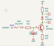
I see the flyback diode but what about the other diode in series with the coil?

Furthermore, when I modelled a 2n3904 with the coil impedance tolerance of a TQ2-L-5V (IK latching..) in spice, I had a large tolerance in the voltage, current and power across the coil? Is this a big concern in the field?

So far I have the circuit attached for driving a non-latching coil with a non-latching SPST switch. Between A and B would be the coil. Is this reasonable? My thinking was to add R48 & 49 to reduce the sensitivity to coil impedance. R47 and C24 set a time constant. 8V is just Vcc after a schottky drop.

1761662223644.png
 
Back
Top