Acoustic Preamp Design - Preamp & EQ

Rpschultz13

Well-known member
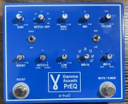
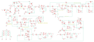
In mid 2023 I started designing my own acoustic preamp, striving for similar functionality to the Grace Designs Alix. I was annoyed by how expensive good acoustic guitar preamp/EQ's are, thought I could make my own cheaper. I started with the preamp section of a Fishman loudbox, added a gain section and then used the ESP State Variable Filters to add:
  • Adjustable Notch/HPF (switch)
  • High and Low shelf filters
  • Sweepable Mid (hi/low switch) parametric filters
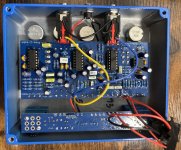
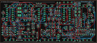
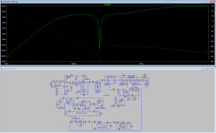
The 14 op amps run on +/- 15v (Felix runs at +/- 18v, Alix/Bix at +/-15). It has 2 boards, the PS board has the 3DPT's and DC/DC converter, other board has the main circuit. I did extensive modeling in LT Spice for all the frequency stuff. I printed the first prototype boards in late 2023, put it together and found 5 design errors. Eventually I fixed all those but it still didn't work, I never could get sound to come out. I lost steam and gave up and started working on Q-tune.

Earlier this year (2025) I took my prototype to a Python workshop to show someone for fun (telling him I never got it to work), he turned the knobs and switches, etc, thought it was cool. Few weeks later I took it home and was going to try troubleshooting again... plugged it in and it WORKED! Evidently one of the switches was routed wrong on 1 side, but he put it in the direction that worked. Talk about luck.

Anyway, so I fixed the 6 different errors on the PCB and printed the next version this spring. I just finished putting it together. It works! I don't have the footswitches wired in yet, and I need to play through it for a while to see how useful the different sections are musically.

IMG_7268.jpg

IMG_7267.jpg

1754247912030.png

1754247933707.png
 
Last edited:
There's a lot going on in there! I'd be interested to know what your design process was: did you breadboard the whole thing, test it in functional blocks, or just go on theory and hope for the best?
 
Way too much to breadboard. In my experience breadboarding often brings more problems than it solves. To each their own, but I'd rather simulate and print (it's cheap), and then fix mistakes and re-print than spend a ton of time breadboarding. There are situations where breadboarding is useful, we did a lot of small circuit R&D breadboarding for Q-tune, then compared with simulations. But for PreQ, breadboarding didn't make a lot of sense to me. I spent a lot of time in LT Spice getting the frequency response I wanted and checking voltages, etc. But mostly went on theory and hoped for the best. All the errors (except the last one) were PCB layout errors, the last one was a schematic error.
 
There's definitely a level of circuit complexity past which breadboards become more a liability than an asset. That said, I don't think I've ever gone full simulation. With more complex circuits, I still end up breadboarding at least some of the functinal blocks.
 
Last edited:
I've talked about this with a few EE's who also hate breadboards, they prefer to solder up perfboard prototypes instead.
 
Hate breadboarding, I inevitably wire things wrong and spend an hour just redoing it. I've had good success with PCB prints. And at the very least with PCB you're more confident that the error is design and not execution which means less places to check.
 
I'm interested in a PreQ-PCB.

My next steps:
1) fully evaluate its function, sound, etc. tweak values maybe. This might take a few months.
2) re-print PCBs fixing all the minor issues I’ve found so far and any improvements.
3) put together parts list and Tayda templates, etc.

Realistically, might be early next year before I get there.
 
Last edited:
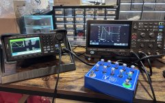
An update, I finally bought a good AWG (arbitrary waveform generator). This AWG and scope combo allows me to create bode plots very easily - the scope tells the AWG what to do via USB (freq range sweep, amplitude, etc). This literally took me 10 minutes to setup and I'm a rookie at this stuff.

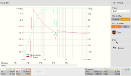
Here's a plot of the notch filter set to about 300 Hz (green trace). Besides the notch, you can see the built in HPF at around 60 Hz. Now I can scrutinize every knob and compare with my spice plots when I designed it. But this is cool, I designed something and it freakin' works! I can't tell you how awesome it is to see results like this.

IMG_7461 1.jpg

SDS804X_HD_PNG_1.png
 
Great work, and I’ll be interested in a board also! Curious as to why you went 15 rather than 18 volt.
Well, it's +/-15 volts, or 30 volts total across the op amps, which many EE's would say is WAY overkill. I've literally argued about this very issue on Allaboutcircuit.com. Me, an ME arguing with EE's, I'm definitely outgunned.

Grace Designs is kinda the pinnacle for acoustic preamp design, they use +/-18v on Felix and +/-15 on Alix and Bix (and I assume Moxi too).

The Aion L5 used a +/-15v DC DC converter, that was my inspiration. I'm using the same one it does. I haven't really considered +/-18. At some point in my testing, I'll test different pickup levels and different gain/vol levels and see if we are anywhere near the top of the headroom. I doubt it.
 
Last edited:
Off the cuff, the opamps could take +/-18v, but I can't find a DC-DC converter that provides that. Options seem to jump from 15 to 24v, and 24v would be over the op amp limit.
 
Very nice job do far! I almost never breadboard either, LTspice typically gets me plenty close enough within two build cycles for the type of stuff I mostly build. I’ve posted a few original acoustic oriented preamp builds here, and have an open source one on GitHub as well.
 
Last night I spent a couple hours measuring the frequency response of each knob/section. I am somewhat shocked, but it all works as I designed. The scope bode plots match what I designed in LT Spice.

Next steps:
1) finish wiring up the footswitches
2) play it for many hours, in different situations and see how useful it seems musically.
3) print v4 of PCB. A handful of minor tweaks, but the biggest problem with v3 is that I used the wrong footprint for the 3PDT so I had to modify the pins to get it to fit in the lower PCB. v4 will fix this.
 
Back
Top