AionFX Redshift Phaser issues

Quirkey

Active member
Damn, I seem to be struggling lately! Trying not to get too discouraged since I did complete some other working things recently that I have yet to post (Hydra, Syncrohwah).

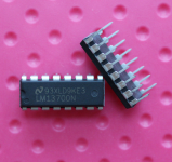
My AionFX Redshift build is not working as in there is no sound when engaged. LEDs light up, secondary switch switches between the two phases. Audio trace shows the signal dying when it hits the first IC (LM13700N). I don't _think_ it's the IC's themselves as they're from a reputable source (Jameco). I have a feeling this is voltage/IC related, but not sure what the correct voltages should be here.

I know there have been some others building this who got it working so any help would be appreciated!
e IMG_7050.jpg
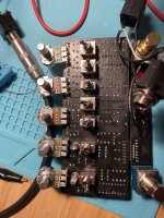
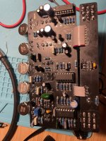
IMG_7049.jpg
 
My money is on the LM13700N.

Have a look at my build report and see the IC casing difference:

I bought a bunch of LM13700N from Aliexpress and they were not the real deal. Either failed to work, or (in a compressor) worked for about 3 minutes before they got too hot and stopped.
I don't have them around, they got thrown in the bin, but I am pretty damn sure that they ended with "KE3".

I could be completely wrong, if you have another pedal to test them in then try that.

On a side note, if you need a UV print for it...
 
My ICs also have a dot on the case at pin 1 like @szukalski

Mine came from Tayda. I’m not saying yours are bad, it could be something else. But I do see a difference. Not sure if it means anything.
 
Tried to breadboard the test circuit but the only issue is that I don't have a working IC to test with to know if my circuit works or its just the IC. I think I'll order some from mouser and come back to this when they eventually arrive.
 
Actually (still up and tinkering even though I have to be up at 5 …) I tried referencing the madbean docs which have the voltage readouts and mine are wildly different. Anyone have a working one they don’t mind probing and posting the voltages for IC1 at least?
 
OK! Finally had time to get back to this tonight. @Dan M my readings are completely off from yours which makes me thing something is wrong with my power section and maybe not the LM13700s ...

1 0.65
2 0.85
3 0.85
4 0.75
5 0
6 0
7 0
8 0.2
9 0.3
10 0.15
11 8.8
12 0.15
13 0.85
14 0.85
15 0.15
16 0.08
 
Wait, 14 and 3 should match. And 11 should be V+.

I must have transposed the right side when I wrote them down:
16 1.3
15 0.5
14 3.6
13 3.6
12 4.8
11 9.0
10 4.8
9 3.6

So your power looks ok on pin 11.
Pin 6 is ground, you could check that for continuity to another ground point.

Your Vb on pin 14 and 3 should be Va X (R44 / (R44+R43)). Which should be 3.52 since your voltage source is 8.8.
8.8 x (10/(10+15)) = 3.52

I would start by tracing the power section, specifically the components leading to Vb.
 
  • Like
Reactions: fig
Yeah, I'm banging my head a little bit - I tried replacing R43 (15K) and same result on the output voltage there. Not seeing any obvious shorts either but it's got to be something around there, right?
 
Run a signal through it for a few minutes, do the ICs get warm and then hot to touch?

That was an effect I saw with the out-of-spec (let's not call them counterfeit just yet) ones I experienced in a compressor.
 
If you remove the ICs from their sockets, and you still have 0.95 V in that part of the circuit, there is something else wrong. (Wrong resistor value, open/cold solder joint, short).

IC2 Pins 14 and 3 should also be at Vb around 3.5-3.6 volts. But I’m guessing they are also 0.85 since your Vb is broken at the voltage splitter R43 and 44.

I would check those voltages on the board with the ICs removed, and go from there
 
Back
Top