Fingolfen
Well-known member
- Build Rating
- 5.00 star(s)
A little over a year ago I posted an article with my hand-etched prototypes of the Dimetrodon Distortion pedal. It basically took the MXR Distortion+ and added a Big Muff tone stack and a gain recovery stage. It was okay, but after I'd built it and tested it, there were problems. It tended to pop a fair amount because of where the volume and gain recovery were located in the circuit. I tried solving this with pull-down resistors, buffers, you name it, but it just didn't quite fix the issue. So I decided to take a step back and see if I could re-engineer the pedal a bit better, and now a year later - it's finally done!
In the interim, I'd done a lot of reading regarding other modifications that had been applied to the venerable MXR Distortion+ circuit. Brian Wampler published a lot of amazing modifications a few years ago in a guitar magazine. I took a few of his ideas and tweaked them for my final design. His mods also included a tone stack, but after breadboarding it, I found it to be very subtle and unremarkable, so I went back to my idea of adding the tone stack from the Big Muff Pi.
An additional problem I ran into then is deciding which Big Muff tone stack I wanted to use. I have recipes for about six of them including Triangle, '73 Ram's Head, '75 Ram's Head, Green Russian, Flat Mids, and Mids bump. I built a couple of prototypes - one the flat mids (which is in the hands of a friend who is going to do a review on it) and one with the '75 Ram's Head stack. I think I prefer the scooped mids of the '75 Ram's Head with the distortion circuit, but the flat mids is also nice. I may ultimately try to do something like what AionFX does with their Halo board and have a mids switch with three settings (scooped, flat, and bumped) - but that's a future project!
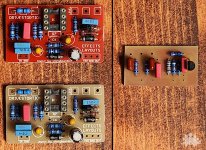
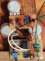
The next issue was taking the pedal from breadboard to functional prototype pedal. For my prototypes, I ended up using an Effects Layouts Drivestortion board and an Effects Layouts Big Muff + gain recovery board that I'd hand etched. Knitting the two boards together took a little bit of work because the circuit diagram of the original Distortion+ was modified slightly. Fortunately the Drivestortion board had room for an extra diode, but I did still have to run two diodes in series with a point to point connection. As you can see from the photo below, the two boards get wired together, one of the pots is attached across R7, and the gain knob is jumpered on the original PCB.
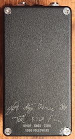
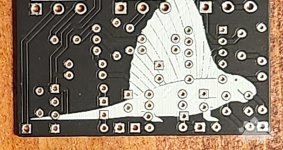
In parallel, I'd been working with my friend in Ukraine, South Obolon FX, and he laid out a single circuit board I could use going forward. The board itself is great, and as you can see from the photos it has a bit of an Easter egg on the back. As with most PCB Easter eggs, it will likely never be seen - especially by the end users - but it's still a fun detail that I've decided to carry through on some of the boards I've been laying out recently.
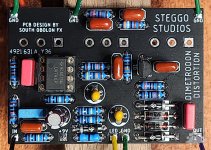
I used essentially the same components to populate both the prototype and monolithic boards. All of the resistors are 1% metal film - a mixture of Yageo and KOA Speer from Mouser. The film capacitors are a bit of a mixed bunch. I a lot of them are WIMA or KEMET, but I had a few old-school Panasonics lying around that I used in the Big Muff tone stack because - why not? Based on the original Effects Layout documentation, it recommended tantalum capacitors for the 1uF caps - so I went that route (and they look cool, so there's that). The IC is socketed as I'm always paranoid about frying one, and I've had a couple of bad ones lately - including a PT2399 I picked up from an extremely reputable source.
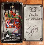
Once the various boards were together, it was time to box them up. For the prototype / multi-board versions - I'd had several enclosures made up with the knob geometry I'd intended to use on the original production version, and with only a little work I was able to fit the spaghetti of the two boards into that enclosure. It gives you a fairly old school look, at least inside, but it's perfectly functional! My Instagram page just hit 1000 followers, so I decided it would be fun to give one of them away.

For both builds I used pretty much my standard hook-up techniques. All of the connections to the jacks - both power and audio - are insulated with heat shrink tubing. The "prototype" versions is using a star ground to the input jack as there are multiple ground wires coming from the boards and it seemed to be the easiest arrangement. It also has three independent power +9V lines running to the main board, tone daughter board, and the LED (which I've put on one of my 3PDT daughter boards so I didn't have to hand wire yet another aspect of the build!). The single board version actually has ground connections for both all of the jacks on the main board, so it's a lot tidier on the inside. I also took the unusual (at least for me) step of including the option of using a 9V battery. I figured since this was an old school pedal, it should have the option of using the "old school" power supply.
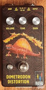
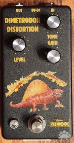
The new enclosure retains the same dinosaur and main art, but adds a different background and control layout to accommodate the new board. I'm honestly not sure which one I like better. The original control layout was sort of unique, but the new design is a bit brighter.
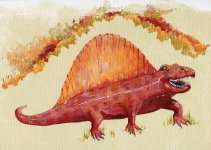
The dimetrodon on the front of the enclosure was originally painted by my wife and I digitized the canvas first in Photoshop and then in Illustrator to transfer it to the pedal. She based the style on medieval illuminated manuscripts - there's more detail at my blog. Last but not least, it is not lost on me that the first original design from a studio dedicated to dinosaurs features... a creature that isn't technically a dinosaur. It lived some 40 million years before the dinosaurs, but often gets lumped in with the latter, so here we are!
As for the sound - the modifications to the gain stack and the addition of the tone control give the pedal a huge amount of dynamic range. Between what I and a few friends have been able to dial in using my prototype - we've gotten anything from Alex Lifeson, to the Scorpions, to Joe Walsh. I'm hoping to have some demos up soon, but my prototype is now living on my pedal board. Granted, it could be a bad case of Ikea syndrome, but so far I've gotten a lot of great feedback from players at my local store and the people who came through the Portland Guitar Pedal Expo earlier this month.
As always - more info at the blog - including more details on the original dimetrodon art! https://steggostudios.blogspot.com/2023/06/a-long-and-winding-development-road.html

In the interim, I'd done a lot of reading regarding other modifications that had been applied to the venerable MXR Distortion+ circuit. Brian Wampler published a lot of amazing modifications a few years ago in a guitar magazine. I took a few of his ideas and tweaked them for my final design. His mods also included a tone stack, but after breadboarding it, I found it to be very subtle and unremarkable, so I went back to my idea of adding the tone stack from the Big Muff Pi.
An additional problem I ran into then is deciding which Big Muff tone stack I wanted to use. I have recipes for about six of them including Triangle, '73 Ram's Head, '75 Ram's Head, Green Russian, Flat Mids, and Mids bump. I built a couple of prototypes - one the flat mids (which is in the hands of a friend who is going to do a review on it) and one with the '75 Ram's Head stack. I think I prefer the scooped mids of the '75 Ram's Head with the distortion circuit, but the flat mids is also nice. I may ultimately try to do something like what AionFX does with their Halo board and have a mids switch with three settings (scooped, flat, and bumped) - but that's a future project!

The next issue was taking the pedal from breadboard to functional prototype pedal. For my prototypes, I ended up using an Effects Layouts Drivestortion board and an Effects Layouts Big Muff + gain recovery board that I'd hand etched. Knitting the two boards together took a little bit of work because the circuit diagram of the original Distortion+ was modified slightly. Fortunately the Drivestortion board had room for an extra diode, but I did still have to run two diodes in series with a point to point connection. As you can see from the photo below, the two boards get wired together, one of the pots is attached across R7, and the gain knob is jumpered on the original PCB.

In parallel, I'd been working with my friend in Ukraine, South Obolon FX, and he laid out a single circuit board I could use going forward. The board itself is great, and as you can see from the photos it has a bit of an Easter egg on the back. As with most PCB Easter eggs, it will likely never be seen - especially by the end users - but it's still a fun detail that I've decided to carry through on some of the boards I've been laying out recently.


I used essentially the same components to populate both the prototype and monolithic boards. All of the resistors are 1% metal film - a mixture of Yageo and KOA Speer from Mouser. The film capacitors are a bit of a mixed bunch. I a lot of them are WIMA or KEMET, but I had a few old-school Panasonics lying around that I used in the Big Muff tone stack because - why not? Based on the original Effects Layout documentation, it recommended tantalum capacitors for the 1uF caps - so I went that route (and they look cool, so there's that). The IC is socketed as I'm always paranoid about frying one, and I've had a couple of bad ones lately - including a PT2399 I picked up from an extremely reputable source.

Once the various boards were together, it was time to box them up. For the prototype / multi-board versions - I'd had several enclosures made up with the knob geometry I'd intended to use on the original production version, and with only a little work I was able to fit the spaghetti of the two boards into that enclosure. It gives you a fairly old school look, at least inside, but it's perfectly functional! My Instagram page just hit 1000 followers, so I decided it would be fun to give one of them away.

For both builds I used pretty much my standard hook-up techniques. All of the connections to the jacks - both power and audio - are insulated with heat shrink tubing. The "prototype" versions is using a star ground to the input jack as there are multiple ground wires coming from the boards and it seemed to be the easiest arrangement. It also has three independent power +9V lines running to the main board, tone daughter board, and the LED (which I've put on one of my 3PDT daughter boards so I didn't have to hand wire yet another aspect of the build!). The single board version actually has ground connections for both all of the jacks on the main board, so it's a lot tidier on the inside. I also took the unusual (at least for me) step of including the option of using a 9V battery. I figured since this was an old school pedal, it should have the option of using the "old school" power supply.

The new enclosure retains the same dinosaur and main art, but adds a different background and control layout to accommodate the new board. I'm honestly not sure which one I like better. The original control layout was sort of unique, but the new design is a bit brighter.

The dimetrodon on the front of the enclosure was originally painted by my wife and I digitized the canvas first in Photoshop and then in Illustrator to transfer it to the pedal. She based the style on medieval illuminated manuscripts - there's more detail at my blog. Last but not least, it is not lost on me that the first original design from a studio dedicated to dinosaurs features... a creature that isn't technically a dinosaur. It lived some 40 million years before the dinosaurs, but often gets lumped in with the latter, so here we are!
As for the sound - the modifications to the gain stack and the addition of the tone control give the pedal a huge amount of dynamic range. Between what I and a few friends have been able to dial in using my prototype - we've gotten anything from Alex Lifeson, to the Scorpions, to Joe Walsh. I'm hoping to have some demos up soon, but my prototype is now living on my pedal board. Granted, it could be a bad case of Ikea syndrome, but so far I've gotten a lot of great feedback from players at my local store and the people who came through the Portland Guitar Pedal Expo earlier this month.
As always - more info at the blog - including more details on the original dimetrodon art! https://steggostudios.blogspot.com/2023/06/a-long-and-winding-development-road.html


