SOLVED! Lowering B+ on a 5F11 Vibrolux clone (fixed bias woes)

coltonius

Well-known member
Ahoy there, fellow amp building enthusiasts.

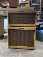
This week I've been going through my very first amp build, a 5F11 Vibrolux kit from Mojotone. Now that I have several amp builds under my belt, I decided it was time to clean up the wiring and do a general safety check. I was reminded that the voltages have been high since I built it, but it's technically within spec at +20%.

It sounds great by the way!

Anyway, I checked the voltages last night and measured B+ at 415v, where 340v is typical. I don't expect to drop B+ by 75 volts, but I'd like to bring it down by at least half! In the past, I have successfully used Rob Robinette's zener diode stack to reduce voltage; both amps were cathode-biased, though. On this amp, the zener stack raised the B+ to 425v! What the shell?! o_O
  • The diodes were oriented correctly, and HV center tap was soldered in the right place. Didn't make a difference.

So here's where I need help:
1. Is it possible to lower the B+ without a bucking transformer? I prefer a solution that is both self-contained and permanent.
2. Why the heck didn't the zener stack work?

**I will retrieve the rest of the voltages later this evening; I don't remember them off the top of my head, but they were all high.

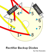
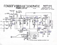
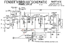
The 5F11 schematic is attached, but here's the RobRob zener diode diagram:
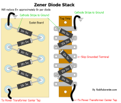
Zener_Diode_Stack.png
 

Attachments

  • 5F11 Schematic.pdf
    43.6 KB · Views: 6
Last edited:
Ahoy there, fellow amp gurus and enthusiasts.

This week I started going back through my very first amp build, a 5F11 Vibrolux kit from Mojotone, to clean up the wiring and do a general safety check now that I have several amp builds under my belt. I remembered the voltages being high when I built it, but it was technically within spec at +20% so I let it be.

It sounds great by the way!

Anyway, I checked the voltages last night and measured B+ at 415v, where 340v is typical. I don't expect to drop B+ by 75 volts, but I'd like to bring it down by at least half! In the past, I have successfully used Rob Robinette's zener diode stack to reduce voltage; both amps were cathode-biased, though. On this amp, the zener stack actually raised the B+ to 425v! What the shell?! o_O
  • The diodes were oriented correctly, and HV center tap was soldered in the right place. Didn't make a difference.

So here's where I need help:
1. Is it possible to get that B+ down without a bucking transformer? I'd like the solution to be self-contained and permanent.
2. Why the heck didn't the zener stack work?

**I will retrieve the rest of the voltages later this evening; I don't remember them off the top of my head, but they were all high.

The 5F11 schematic is attached, but here's the RobRob zener diode diagram:

View attachment 71133
Rather than dropping, I would start at the source and find out why the b+ is running hot like that. Is it the tranny or rectification? Just my two cents.
 
Ahoy there, fellow amp gurus and enthusiasts.

This week I started going back through my very first amp build, a 5F11 Vibrolux kit from Mojotone, to clean up the wiring and do a general safety check now that I have several amp builds under my belt. I remembered the voltages being high when I built it, but it was technically within spec at +20% so I let it be.

It sounds great by the way!

Anyway, I checked the voltages last night and measured B+ at 415v, where 340v is typical. I don't expect to drop B+ by 75 volts, but I'd like to bring it down by at least half! In the past, I have successfully used Rob Robinette's zener diode stack to reduce voltage; both amps were cathode-biased, though. On this amp, the zener stack actually raised the B+ to 425v! What the shell?! o_O
  • The diodes were oriented correctly, and HV center tap was soldered in the right place. Didn't make a difference.

So here's where I need help:
1. Is it possible to get that B+ down without a bucking transformer? I'd like the solution to be self-contained and permanent.
2. Why the heck didn't the zener stack work?

**I will retrieve the rest of the voltages later this evening; I don't remember them off the top of my head, but they were all high.

The 5F11 schematic is attached, but here's the RobRob zener diode diagram:

View attachment 71133
What voltages are you getting on all taps(filaments included)?
What kind of rectifier tube are you using? Country of origin?
Are there multiple primary voltage taps?
 
Rather than dropping, I would start at the source and find out why the b+ is running hot like that. Is it the tranny or rectification? Just my two cents.
What voltages are you getting on all taps(filaments included)?
What kind of rectifier tube are you using? Country of origin?
Are there multiple primary voltage taps?

My wall voltage consistently hovers around 120v, and right now it’s at 121.5v.

___
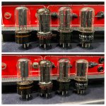
I’ve tested 4 different 5Y3GT rectifiers with the following results:
  1. NOS Motorola (416v)
  2. NOS Motorola (412v)
  3. NOS Sylvania (411v)
  4. NOS Tung-Sol (415v)
Tubes 2-4 are US made. Fair to say Motorola 1 is also US?

IMG_7245.jpeg

___
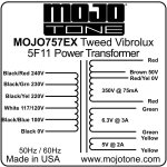
The Transformer is MOJO 757EX, using the black (0v) and white (117/120v) primaries.

IMG_7241.jpeg

___
Voltages:
  • PT primary black to white: 123v
I’ve wired the recto with two “protection diodes”, per Rob’s site. The diodes are oriented correctly, and I’ve done this on all my subsequent amp builds with no issues (including the ones where the Zener diode trick did work to lower the B+).
  • Red > Red is 716v (in the photo below it would be pins 3 and 5)
  • Red > HV center is 359v on both sides
  • Red + diode > HV center are 189v (pin 4) and 191v (pin 6)
  • Heaters are 6.5v AC
IMG_7248.png
___
Amp voltages are as follows:
IMG_7251.jpeg

Did I miss anything? :)
 
Had to ask about the rectifiers as some older Russian 5Y3 were essentially rebadged 5AR4
seeing your filament voltages up, but not super high says you could be safe losing a bit on the primary. Doesn’t look like you have any more higher taps that would essentially bring it down. Although you could use the 100v tap and say the 220 or 230v tap which should bring it down, but not sure how the transformer is wound and if it can take the current on the 200+v windings. you would need to ask the folks at mojo or heyboer if the transformer can take that.folks did that all the time with the Hammond iron in the late 90s/early2000s, but arguably, few companies iron is as robust as Hammond
 
Hi, long time lurker here and not very active as a poster but I might be able to help. I've been designing and building amps for a long time now, so I've had a lot of experience with modern power transformers.

Your issue is going to be the much lower coil resistance in the newer transformers vs the ones spec'd to run at 110 or 115. A 350 VAC secondary is way too high for 6V6s to draw enough current to bring the secondary into spec. 316-320 VAC is probably where that secondary should be, and maybe even as low as 290 VAC.

Zener Voltage Drop KitGranger Amps makes a nice little PCB you can put in your amp that will reduce the voltage however much you want: Zener Voltage Drop Kit

$22 plus shipping, so not as cheap as Rob's solution but this one is super compact and works every time.
Thank you for this!

I'm familiar with the difference between vintage and modern wall voltages; I've had to dial in a lot of voltages to get things right on some of my builds! In every case, they started off as too high.. I still can't wrap my head around why the zener method I tried didn't work, but I'm going to check out that PCB solution you linked and continue my research.

I'll report back here once the PCB is in and again if I find information on the failed zener method.. Because my curiosity is going to kill me if I don't!


Thank you for all for the troubleshooting help! Stand by for updates.
 
Last edited:
I often find that PTs in my builds have too high a B+. Whenever I've queried it with the supplier they's always said it's fine. But really?? That's one reason why I used a lower B+ PT from MM in my last few 5E3 builds, and the results have been spectacular. I would like to build anther 5F11 one day because it's one of my favourite circuits, but I'm not sure if MM make a lower B+ version off the shelf. Still, they usually sound pretty good with the stock 5F11 PT...

This can be a real issue in amp building.
Yep. I’ve gotten a few PTs that were close enough to compensate with dropping resistors, but I try to find the “lower B+” model whenever possible.

Looks like MM does have one of those for the 5F11, by the way. The FTVP has unlisted B+, but the FBVP lists 320v instead of the Mojo’s 350v. It also looks like they forgot to put a premium price tag on it at $139, so it begs the question of whether I should leave well-enough alone with this one and try to build a second, more accurate 5F11 with the lower B+ in a combo with a 10”.

It’s not like this is vintage accurate with a 12” GA-SC59 anyway:

IMG_4101.jpeg
 
Update!

The Good News:
I installed the Granger kit, and all of the voltages are dead-on. B+ is ~330v, and everything down the line is where it should be.

The Bad News:
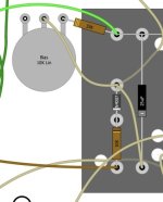
The bias supply needs some MAJOR tweaking. The Granger kit said this might be the case, but it's not as straightforward as I had hoped. To keep things clear during my explanation, I'll post a schematic with enumerated designations for the resistors in question:

5F11 schematic.jpg

Note that the 10k pot + 33k resistor = R2 on the schematic. With the higher B+, this worked effectively to bias the power tubes.
5F11 layout - negative bias supply.jpg

Right now, the 6V6 pair is drawing.. 1mA, where 25.5mA is 60% dissipation. I'm measuring this by clipping leads on either end of a 1Ω resistor between pin 8 of each power tube and ground. In my amp, R2 is a 39k resistor + a 10k bias pot, so I thought that lowering the 39k to 15k or even 10k would help. You already know it didn't.
  • Side Note: I discovered that lowering the total resistance of R2 too much caused R1 to release its mojo in a puff of smoke. Mojotone originally supplied a 1/2w carbon comp for that position, even though other amps call for 1w or 2w.

The tweed Vibrolux's next of kin is a 6G2 Princeton, and one of the minor differences is the value of R1 (100k instead of 10k). Since tweaking R2 didn't work, I'm going to change my toasted 10k to a 2w metal oxide 100k. Hopefully that helps!

(If anybody has other suggestions, I'm open to those as well. If the 100k resistor doesn't work I'll be lost all over again.)
 
Last edited:
Another update: After testing with various combinations of R1 and R2, I decided to remove the ZDK to ensure everything still works as it was.. And sure enough, it’s back to purring like a kitten! A kitten that’s running a full 70-80 volts higher B+ than expected, just like before.

I kind of wonder whether the PT isn’t fucked up in some way that makes these attempts ineffective. I’ll email Granger and see what he has to say..

Mojotone wanted me to remove the protection diodes from the rectifier (see OP) before they began helping me troubleshoot, as if that’s going to make a 90v difference. :rolleyes: Perhaps I’ll do it to see what they have to say as well. (I’ll put $100 on some variant of, “Sorry, you’ll just have to live with it.”)

May as well since it’s already on the bench with alligator clips spilling from its insides! I’m starting to feel like this though:

1712111535635.gif
 
Last edited:
I posted my problem over on TGP and got many helpful suggestions, as well as a technical explanation for what's going on.

First, the explanation, as given by bmc0 here:

"When you lower the B+ by way of the center tap, what you're actually doing is creating a negative voltage offset at the center tap relative to ground. If you have, for example, a string of zener diodes that drops 60V between ground and the center tap, the center tap will be at -60V whenever the HV rectifier is conducting (near the peak of each half cycle).​
Now what about the bias tap? The RMS voltage between the bias tap and center tap is still the same, of course, but there's a DC offset of -60V relative to ground. For a 50V tap, instead of approximately ±70V peak relative to ground, you get +10V/-130V. Result: your -36V bias supply ends up being something like -64V, biasing the power tubes well into cutoff.​
This also explains why your B+ went up with the zener diodes. With the power tubes biased around 23mA each, the total power supply sag is around 110V (both rectifier and copper losses are quite high). If the power tube bias current drops to almost zero, the sag is more like 40V. Net, you gain about 10V by trying to drop 60V at the center tap.​
There's a simple solution which @Dan40 already mentioned: put the zener diode string between the 5Y3 and the first filter cap. This will drop the B+ without affecting the bias supply. Note that the cathodes go toward the rectifier in this case. If you connect them the other way, you'll only get ~0.6V of voltage drop per diode."​
__________________________________________________
All of the solutions provided involve leaving the HV Center tap connected to ground and adjusting the voltage between the rectifier and the first filter cap:
  • 10w 1k resistor between the rectifier and the first filter cap.
    • Note: The value given was for my amp specifically. Your value may vary!
    • the resistor should be aluminum chassis mounted with thermal paste applied between the resistor and chassis.
  • Stud-mounted Zener diode that mounts to the chassis between the rectifier and the first filter cap
    • make sure the specs align with the need (orientation of the anode/cathode; wattage rating; voltage rating)
  • RobRob zener stack... between the rectifier and the first filter cap
  • New power transformer
    • Okay, so that's a joke.. Sort of. I miss ClassicTone's "lower B+" PTs, but Mercury Magnetics also has a few with this feature.
In ALL cases, the power tubes should be re-biased.

I haven't had a chance to try any of these, but hopefully somebody can benefit from this info! Here's a link to the original thread, in case new information pops up later:

Lowering B+ on a 5F11 Vibrolux clone (fixed bias woes)

I think this is my fault. Your PT is perfectly fine.

I really should have mentioned specifically where to install that kit. You can only install the kit off the center tap reliably if you're dealing with a cathode biased power section which will not have this issue, otherwise you can easily run into the issue you're describing.

Put the kit after your rectifier and before the first filter cap. Then you'll want to make sure your bias circuit is back in working order and see if you can get things back to where you want it.

The final step is to measure your preamp B+ nodes again and make sure they're close to the schematic. If anything is really far off you may want to order some 2W power resistors. Anything less than 2W, and generally metal oxide or carbon film (over-voltage / wattage properties) is not a great idea no matter what Fender did.

Also, what HBP mentions in the last post of that TGP thread about PTs is what I was alluding to earlier in this thread about power transformers manufactured today. It's not just wall voltages, it's the size of the wire in the windings and the different resistances they produce vs the originals. Mercury Magnetics is usually meticulous enough to use the same gauge as originals but they don't publish primary or secondary resistances so it's difficult to really know what you're getting until it's on your bench and you can take measurements.
 
Last edited:
I think this is my fault. Your PT is perfectly fine.

I really should have mentioned specifically where to install that kit. You can only install the kit off the center tap reliably if you're dealing with a cathode biased power section which will not have this issue, otherwise you can easily run into the issue you're describing.

Put the kit after your rectifier and before the first filter cap. Then you'll want to make sure your bias circuit is back in working order and see if you can get things back to where you want it.

The final step is to measure your preamp B+ nodes again and make sure they're close to the schematic. If anything is really far off you may want to order some 2W power resistors. Anything less than 2W, and generally metal oxide or carbon film (over-voltage / wattage properties) is not a great idea no matter what Fender did.

Also, what HBP mentions in the last post of that TGP thread about PTs is what I was alluding to earlier in this thread about power transformers manufactured today. It's not just wall voltages, it's the size of the wire in the windings and the different resistances they produce vs the originals. Mercury Magnetics is usually meticulous enough to use the same gauge as originals but they don't publish primary or secondary resistances so it's difficult to really know what you're getting until it's on your bench and you can take measurements.
Hey, it's not your fault at all. Between this thread and the one on TGP, I have the solution and the "why" behind it! The kit recommendation was a good one- it's way less bulky than the diode stack and now I know where to install it.

3rd bonus! The information is now here for future DIY amp builders. As a teacher, that's important to me. I scoured the internet for several hours across multiple days before starting any threads. I knew going in that cathode-biased amps were easiest to manipulate but fixed bias seemed nebulous. Suggestions on other forums (Amp Garage, et al.) seemed incomplete or not quite analogous to my situation.

Re: Mercury Magnetics: I've heard they are forthcoming with information when asked, but it would be more convenient if they already had everything on their site!
 
I'm glad you got it resolved!

Re: Re: Mercury Magnetics: Dave Hill is the guy you usually talk to when you call or shoot them an email and he's super helpful with specs.

For more future reference, for those that have access to a Windows PC there's this tool: Duncan PSUD2. This will let you plug in your rectifier specs, transformer primary/secondary voltage and filter chain and calculate your approximate voltage at the various B+ nodes. It's really helpful to give you an idea of what the unloaded AC voltage is you need to target at say 120 VAC average line voltage to be in spec. It's not 100% accurate unless you have the PT in your hand and have all the measurements, but it's close enough to plan your power stage around it.
 
Back
Top