Anderton's EPM: Project #24...

Coda

Well-known member
Phase 1, in which Doris gets her oats....

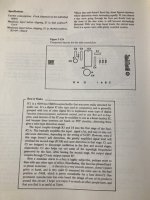
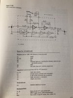
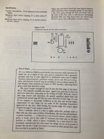
I have decided to build Craig Anderton's Tube Sound Fuzz, from his Electronic Projects for Musicians. Here are the pages that cover the project:
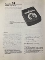
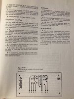
88D77CF4-8EBD-436E-8C26-34DB5856EE77.jpeg 4AE9FA48-77CE-4430-993F-0E7715DA53B9.jpeg 8B0A1A57-B857-40DC-ADDF-37DC405FD35D.jpeg 608A6BAA-D32A-4EE6-986D-19B3768A042E.jpeg

I am posting the pages without permission...but this is for "pedalogical" purposes, so its ok. Besides, Anderton obviously ripped off Way Huge...

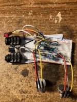
First step in the project was to order all of the parts. Step two is to breadboard the circuit (seen below):
0C69F2FB-D2CE-4338-B637-13589239AC17.jpeg

A few observations: this thing is super loud. Also, Tube Sound FUZZ???...more like Tube Sound Classic Rock distortion. This is a very meaty, round, od/light distortion. It definitely has a bit of bark to it. Now that I know it works, and that I like the circuit, the next step will be the vero layout. The next update will deal with that, and maybe the assembly too...
 

Attachments

  • 8B0A1A57-B857-40DC-ADDF-37DC405FD35D.jpeg
    8B0A1A57-B857-40DC-ADDF-37DC405FD35D.jpeg
    66.1 KB · Views: 4
Part II:

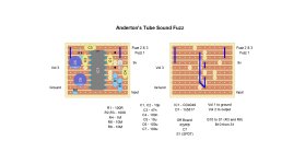
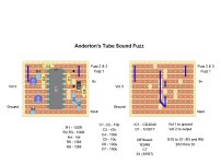
The only layout that I have been able to find is this one from Parasit Studio:

1115391.gif


Unfortunately this version of the circuit features a mod. The toggle has been removed, and an additional resistor was added between the input and ground (pulldown). There is also a link between pins 13 and 14, which is not in the schematic. I am going to do my best to use the above layout as a template, but redesign what is needed to bring it back to the original...

Update:

Tube Sound Fuzz Layout.jpg
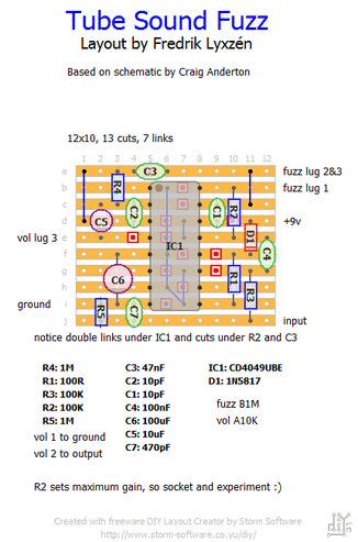
Above is my layout. I couldn't figure out how to make the components smaller. I decided to wire the caps connected to the switch off-board, same with C7. Next step is to order those 10p caps I'm out of...
 
Last edited:
Part II:

The only layout that I have been able to find is this one from Parasit Studio:

1115391.gif


Unfortunately this version of the circuit features a mod. The toggle has been removed, and an additional resistor was added between the input and ground (pulldown). There is also a link between pins 13 and 14, which is not in the schematic. I am going to do my best to use the above layout as a template, but redesign what is needed to bring it back to the original...

Update:

View attachment 31145
Above is my layout. I couldn't figure out how to make the components smaller. I decided to wire the caps connected to the switch off-board, same with C7. Next step is to order those 10p caps I'm out of...
If you're using DIY Layout Creator you need to double click on the component and a popup will open. Update the height/width to make it look neater
 
Doesn’t the schematic have a switch in there?

Edit: I see it in the notes. Nvm

The layout I used as a template ditched the toggle and went with a set value. I want the toggle, so I’m putting those resistors on the switch, and will wire them to the black dots on the layout….

I started building earlier. I marked the cuts, made the cuts, added the links (I don’t know if this is the proper way to start but from what I have read, there are only guidelines, no rules). I then installed the socket, but something looked off. Then I realized that, with incredible luck, I happened to grab a 14 pin socket, not a 16 pin one. One 14 pin socket in a drawer of about 30 16 pin sockets. Maybe I’ll go get a lottery ticket…

Anyway, it doesn’t matter at the moment, mistake or not. My Stompboxparts order that was due total was in Jacksonville, FL, this morning…and I am in NJ…
 
Any update on yours? I have some time this weekend and want to at least breadboard this.

I’m at strike two so far. Started fresh, with the correct socket, got everything populated, wired it up…nothing. I haven’t had time to trouble shoot yet. There are so many potential causes that it’s a bit overwhelming…
 
  • Like
Reactions: fig
What helped me when I made my layouts for the first time to trace the circuit a bunch of times. Trace the power, ground, and signal paths and make sure there’s no overlap. Check all your track cuts to make sure they’re completely severed. Stripboard is very forgiving with solder so make sure you’ve got good joints and all the tracks on between are solder free. Stray solder is usually the culprit for me. Then probe the circuit to find the dead spot.
 
I got it populated last night, but was too tired to test it, so I just did and had a couple of misfits but that's all sorted. I laid it out a bit differently and powered the whole rail through the 100Ω ( ~ 7.6v ) to make connections simpler.

KmYhfzF.jpg


Edit: Oh yeah, no LEAD / RHYTHM switch. I was thinking about a latching FS for that bit. (y)

A little more info; the 10mΩ LEAD resistor delivers ~ 2.6v to the trimmer whereas the 100kΩ RHYTHM only serves ~ 1.5v. I’ve got some scope shots to load but suffice to say the FUZZ pot will do very little when in the LEAD position.
 
Last edited:
No rush, I just had some time and it’s a good sounding pedal. I‘m leaving out the 10mΩ option though. The 100kΩ gives a nice manageable breakup with more volume than I’ll ever need -unity being around 1.5 on the VOL pot.
 
No rush, I just had some time and it’s a good sounding pedal. I‘m leaving out the 10mΩ option though. The 100kΩ gives a nice manageable breakup with more volume than I’ll ever need -unity being around 1.5 on the VOL pot.

It is a very loud circuit, I was surprised at that. Im going with the toggle because I want to stick to the original design. If/when I do a second one, I think I would eliminate the Gain control and wire it maxed…and maybe put the toggle on a footswitch.
 
What helped me when I made my layouts for the first time to trace the circuit a bunch of times. Trace the power, ground, and signal paths and make sure there’s no overlap. Check all your track cuts to make sure they’re completely severed. Stripboard is very forgiving with solder so make sure you’ve got good joints and all the tracks on between are solder free. Stray solder is usually the culprit for me. Then probe the circuit to find the dead spot.

I figure that it’s either too much/not enough solder. That, or I miswired something. I wasn’t too comfortable with the footswitch schematic I found…
 
Back
Top