Arachnid 2.1 Build - No Wet Signal [SOLVED]

Cybercow

Well-known member
Is there an image of the Arachnid 2.1 PCB with the component identifiers (not values) that matches the schematic?

The build docs and website sales page shows only the component values on the shown\available PCB images. I believe I'll have greater success troubleshooting my "no wet signal" issue on this Arachnid 2.1 build with an image of the PCB that shows the component identifiers (with or without the component values).

Engaged, the LED lights and the pedal conducts proper "Mix" and "Volume" control - just no 'wet' signal.
I've already double-checked continuity of the FV-1 pins to the PCB - OK.
The +9v, Vref and 3.3v voltages at the FV-1, EEPROM and center pin of the rotary switch are good.
Also tried using the internal (default) patches by shorting pin 13 of the FV-1 to ground.

It's just a bear trying to troubleshoot without visual reference between the schematic and PCB. Thanks for reading.
 
Last edited:
Still not able to find the issue. When ever the mix is turned all the way to the right (effect only) there is no sound. And with the Mix pot set to the far right, I cannot get any signal to pass thru my audio probe when the probe is connected directly to the pedal output jack and any other signal point in the circuit. I've tried other TL074 & TL084 ICs - nothing.

So far . . . .
• Engaged, the LED lights and the pedal conducts proper "Mix" and "Volume" control - just no 'wet' signal.
• I've already double-checked continuity of the FV-1 pins to the PCB - OK.
• The +9v, Vref and 3.3v voltages at the FV-1, EEPROM and center pin of the rotary switch are good.
• Also tried using the internal (default) patches by shorting pin 13 of the FV-1 to ground.

Is there a voltage chart for the Arachnid 2.1 build?
 
Can you audio probe the input of the fv-1 (pin1)? How about the output (pin28)? For these tests, plug your guitar into the input jack and use the audio probe to check for signal at pin1 and pin28. This would tell you if the fv-1 chip is losing your signal or if it’s another part of the circuit.

make sure your audio probe has a capacitor to block dc voltage (any useful audio probe should).
 
I had a bad FV-1 ordered from a seller through AliExpress. Most likely not the same seller you used, but there are bad FV-1 chips in the marketplace.

Take phil1's suggestion and use an audio probe to see if you have signal going in at pin 1 and out on pin 28. That's the best way to see if it is the chip and not a problem in the circuit.
 
Can you audio probe the input of the fv-1 (pin1)? How about the output (pin28)? For these tests, plug your guitar into the input jack and use the audio probe to check for signal at pin1 and pin28. This would tell you if the fv-1 chip is losing your signal or if it’s another part of the circuit.

make sure your audio probe has a capacitor to block dc voltage (any useful audio probe should).

Thanks for those suggestions. I'm well verse in the use of an audio probe, I just made and use mine a bit differently. It's just a 0.1µF 250 V cap with a 3" wire and gator clip at one end and 6" of wire with a 1/4" exposed (tinned) tip on the other. I usually connect the pedal's output up to an amp and guitar (or sig\gen) connected to the pedal's input. Then I connect my audio probe's gator clip to the output jack tip and can poke around that way.

However, when the pedal is engaged and the Mix control cranked all the way to the right (effect only), I get nothing when I touch the other end of the probe ANYWHERE in the circuit. When I repeated the probing a second time, I did not connect the amp to the pedal's out put jack, rather I grounded it and connected the gator clip to the tip of cable going to amp. In that manner, I was able to get a signal to the amp at the pedal's input jack all the way up to pin 1 of the FV-1. So signal IS getting to the FV-1. However, at pin 28 of the FV-1 - nothing. I even shorted pin 13 of th FV-1 (at the correct side of R5) to ground in order to access the internal algorithms - still nothing. There is something about the Mix control using Vref that I don't get and don't understand why I cannot get a signal to the output even when I jumper my probe directly across the pedal input to the out put. That's why I disengaged the direct amp connection to the pedal and let the auto probe supply the connection.

With the Mix control set at anything less than the extreme right-hand turn position, clean signal does pass thru the pedal when engaged. That suggests the quad opamp is good.

Further, I double checked all the resistor & cap values and there continuities surrounding the FV-1 pins and to the opamp and EEPROM. I even double checked the continuity from the 8-way rotary switch to ground & the diodes and the diodes to pins 16, 17 & 18 of the FV-1 - all good.

I know there are a lot of bad actors out there on AliExpress and eBay, but with this seller on AliExpress having thousands of sales with 99.9% rating, I thought the odds of getting good FV-1s were excellent. I have since filed for a refund and the seller has agreed to do so.

I already clipped out the 1st FV-1, cleaned up the FV-1 PCB pads and replaced it with the second of the three I purchased. I then double-checked that all 28 pins had good continuity to their respective circuit connection points. The +9v, Vref (4.5v) and +3.3v are all good, and I used a DSO38 mini-digital scope to ensure the crystal was operating. I got my crystals from PedalPCB, so I'm pretty sure those are good.

So, it seems I'm left with bad FV-1s from that vendor. Unless someone else has other suggestions, ideas, I'm probably gonna have to wait for my next FV-1 order from PedalPCB.

And I gotta say, PedalPCB PCBs are of pretty good quality and they seem to take the heat very well, considering all the soldering, unsoldering & desoldering I've done thus far. And the updated docs with the component identifiers clearly marked on the PCB image was a big help. Thanks! Kudos to PedalPCB!
 
Gotcha. Couldn’t tell from you first post what you had tested with the audio probe.

I agree it’s strange about no pointin the circuit getting signal to the output jack (although after reading it I’m still not sure I completely understand your setup).

one last idea to try... with the fv-1 totally I’m disconnected from pcb, put the mix knob at max wet. Plug the pedal output into the amp. Connect your guitar to one end of the audio probe and connect the other end of the audio probe to MIX 1. See if you get output that way. Since the fv1is disconnected, there’s no chance of a bad fv1 affecting your signal this way.

the mix2 to vref connection just pulls either the dry or wet signal closer to vref. Think of it like a voltage divider where the 15k Resistor and half of the mix knob make up the voltage divider. Like how a volume knob is a voltage divider. As far as Audio signal is concerned (AC voltage), vref acts like ground.

Excellent approach! Hadn't though of that. Will give that a go. Applying an input after C8 will isolate the FV-1 completely and expose any potential issues with the Mix & output section.

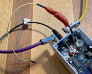
And FYI, here's the audio probe setup I typically start with . . . .

Arachnid2_ProbeTest1.jpg
 
Thanks for those suggestions. I'm well verse in the use of an audio probe, I just made and use mine a bit differently. It's just a 0.1µF 250 V cap with a 3" wire and gator clip at one end and 6" of wire with a 1/4" exposed (tinned) tip on the other. I usually connect the pedal's output up to an amp and guitar (or sig\gen) connected to the pedal's input. Then I connect my audio probe's gator clip to the output jack tip and can poke around that way.

There is a problem with this method. Many pedals have a very low output impedance. The Arachnid's output impedance is 100 Ohms at audio frequencies due to IC1-4, R12 and C15. If you clip your probe at the output jack, everywhere you probe will be loaded down with 100 Ohms when the pedal is engaged.
 
There is a problem with this method. Many pedals have a very low output impedance. The Arachnid's output impedance is 100 Ohms at audio frequencies due to IC1-4, R12 and C15. If you clip your probe at the output jack, everywhere you probe will be loaded down with 100 Ohms when the pedal is engaged.

I've been using an audio probe in this manner for over 40 years and never had a problem. I just pulled out an Arachnid 1.0 build I have on my pedalboard and verified that connecting my probe in this manner had no problems rendering (delivering) the signal. Connected thus, I was able to verify there is signal at the FV-1 on input pin #1 and the output pin #28. I also checked pins #1 & #7 on IC5 with no issues. I also decoupled the output jack, grounded the sleeve and checked those same points with the same results. So, while "theory" may suggest there will be a problematic loading, practical application suggests otherwise.
 
Last edited:
one last idea to try... with the fv-1 totally I’m disconnected from pcb, put the mix knob at max wet. Plug the pedal output into the amp. Connect your guitar to one end of the audio probe and connect the other end of the audio probe to MIX 1. See if you get output that way. Since the fv1is disconnected, there’s no chance of a bad fv1 affecting your signal this way.

the mix2 to vref connection just pulls either the dry or wet signal closer to vref. Think of it like a voltage divider where the 15k Resistor and half of the mix knob make up the voltage divider. Like how a volume knob is a voltage divider. As far as Audio signal is concerned (AC voltage), vref acts like ground.

I ran the test as you suggested and I do get output. That suggests that the section after the FV-1 is fine. When I rotate the Mix pot, it comes and goes with the sweep. Less to none at the far left extreme and and gets louder as I sweep the Mix pot to the right, with little change past the mid-way setting. Kinda suggests the FV-1 is a dud. I get signal to the FV-1 at pin #1, but nothing at pin #28 on the FV-1. Bummer.

And thanks for the explanation of how that Mix control works. I suspected as much, but had not seen that method employed before and I couldn't make confident sense of it. Pretty slick.
 
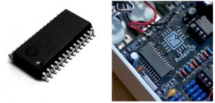
Sorry for not chiming in on this sooner, but something just caught my eye in your pic.

That is definitely not a genuine Spin FV-1 IC, check out the placement of the Spin logo on the IC.

FV1.jpg
 
Thanks for the confirmation. Lesson learned. The vendor has over 33,000 sales with a 99.9% rating. Thought it would be a valid purchase during the extended 'out-of-stock' issue on the FV-1 availability. Lesson learned. Glad the vendor was willing to apply a full refund. Adding what I need to my PedalPCB cart.
 
Back
Top