Basic Workflow Tips for Building a PedalPCB

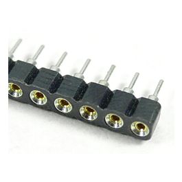
You can also use your cutters to cut them to length. I found it worked best when you do it quickly with force, a nice brisk snip.
 
I’ve tried knife vs cutters; I used to prefer the snips for the SIPs, but currently I’m getting best results with the xacto knife, sliding* the blade forward as I press down (*sawing implies back and forth).

I get much less exposed pins/breakage than with cutters; perhaps due to better and more consistent control of the angle of the blade compared to cutters. That may change…
I just clamp where I want to snap with needle nose pliers and snap it off with my fingers, singles or doubles I use another pair of pliers
 
I just clamp where I want to snap with needle nose pliers and snap it off with my fingers, singles or doubles I use another pair of pliers

I’ve had SIP sockets from several manufacturers, none had the ability to snap off by hand cleanly. Some cheap stuff uses brittle plastic, more expensive product can be more flexible, but either way for exactly those reasons (too brittle/too flexible) the breaks are not clean and waste a lot of pins.

For example:

3BCF84D0-3933-4361-B9FD-4625B32285B2.jpeg

I won’t use the sockets with exposed pins, I’ll pop out the exposed pins and save those pins for other uses.

You can see the silver SIP socket row on the far right didn’t clip cleanly, there’s some plastic protruding that I’ll shave off for the next bit that I use. The 4-wide SIP with the two centre pins removed is what I use for diodes and resisters experimentation; the silver 4-pin with one exposed pin will be reduced to 3-pin for socketing a transistor or 3-wide with centre-pin removed for socketing a film cap; the gold 3-pin with exposed pin will be narrowed to 2-pin for socketing an electrolytic or LED, etc.

I use the sockets extensively because I like to experiment, can’t make a decisive choice (“what if I change my mind down the road?”), and don’t breadboard enough — but that’s changing, I’m doing a lot more breadboarding now, spurred on by BtR, CdB, fig and others.

Not just breadboarding, but for many other aspects of the hobby, I have to say this forum and members such as yourself have been a good influence on me.
 
I’ve had SIP sockets from several manufacturers, none had the ability to snap off by hand cleanly. Some cheap stuff uses brittle plastic, more expensive product can be more flexible, but either way for exactly those reasons (too brittle/too flexible) the breaks are not clean and waste a lot of pins.

For example:

View attachment 24392

I won’t use the sockets with exposed pins, I’ll pop out the exposed pins and save those pins for other uses.

You can see the silver SIP socket row on the far right didn’t clip cleanly, there’s some plastic protruding that I’ll shave off for the next bit that I use. The 4-wide SIP with the two centre pins removed is what I use for diodes and resisters experimentation; the silver 4-pin with one exposed pin will be reduced to 3-pin for socketing a transistor or 3-wide with centre-pin removed for socketing a film cap; the gold 3-pin with exposed pin will be narrowed to 2-pin for socketing an electrolytic or LED, etc.

I use the sockets extensively because I like to experiment, can’t make a decisive choice (“what if I change my mind down the road?”), and don’t breadboard enough — but that’s changing, I’m doing a lot more breadboarding now, spurred on by BtR, CdB, fig and others.

Not just breadboarding, but for many other aspects of the hobby, I have to say this forum and members such as yourself have been a good influence on me.
Guess I'm just lucky that way, never had any of those issues
 
I’ve had SIP sockets from several manufacturers, none had the ability to snap off by hand cleanly. Some cheap stuff uses brittle plastic, more expensive product can be more flexible, but either way for exactly those reasons (too brittle/too flexible) the breaks are not clean and waste a lot of pins.

For example:

View attachment 24392

I won’t use the sockets with exposed pins, I’ll pop out the exposed pins and save those pins for other uses.

You can see the silver SIP socket row on the far right didn’t clip cleanly, there’s some plastic protruding that I’ll shave off for the next bit that I use. The 4-wide SIP with the two centre pins removed is what I use for diodes and resisters experimentation; the silver 4-pin with one exposed pin will be reduced to 3-pin for socketing a transistor or 3-wide with centre-pin removed for socketing a film cap; the gold 3-pin with exposed pin will be narrowed to 2-pin for socketing an electrolytic or LED, etc.

I use the sockets extensively because I like to experiment, can’t make a decisive choice (“what if I change my mind down the road?”), and don’t breadboard enough — but that’s changing, I’m doing a lot more breadboarding now, spurred on by BtR, CdB, fig and others.

Not just breadboarding, but for many other aspects of the hobby, I have to say this forum and members such as yourself have been a good influence on me.
Happened to me a couple of times. I now use razor blade to cut the socket strips and it makes a nice clean cut. Never had any problems since.
 
Step 2: Prep
Clean your PCB. I use isopropyl alcohol and a paper towel.
fig. 6
View attachment 1336

Step 3: Audit components & populate the board
With your digital multimeter measure all components for proper value before adding them to the board.
fig. 7
View attachment 1360

A flux pen is recommended. It will help you avoid any future potentially fouled solder joints. Turn the board over and flux the pads which you will be soldering. Do this in small areas at a time so you don't get flux all over yourself.
fig. 8
View attachment 1337

Clean your leads
Again, isopropyl alcohol and towel here.
fig. 9
View attachment 1358
Or...

Flux your leads...the area that will touch the PCB pads when properly seated. Start at the component and go out about 1/8".
fig. 10
View attachment 1365

Bend the leads. I like to hold the resistors down and bend the leads away from each other a bit so they stay in place when turning the board over.
fig. 11
View attachment 1342

Another option is to use blu-tack or poster putty. When using this, try to not smash it down too close to the resistors or it will touch the exposed leads and melt when soldering. I find this method particularly useful when populating box film caps and sockets so they go on straight and tidy.
Solder time
Most people have preferred temps, tips, and solder, but for the sake of this guide, what I used is a fine point chisel tip in an iron set to roughly 700°F (370°C) and Kester .80mm 63/37 "no-clean" solder. This is not a definitive guide, rather just my current preference.

Low profile components go in first, i.e. resistors, diodes, next are sockets, trimpots, then film capacitors and electrolytics. Clip the leads after soldering each component or area of components.
fig. 12
View attachment 1343
fig. 13
View attachment 1361

...continued below
Many thanks for this. How hot do you have your soldering iron and do you have any advice if the solder either balls up on the component leg or creeps up the iron instead of flowing through the PCB?
 
I keep mine as hot as it gets. Make sure the tip is clean. If it looks dark, add solder to it and wipe it with a brass sponge. It should look shiny. That helps with heat conduction.

I follow a very simple soldering approach: apply heat to the component leg and PCB pad at the same time with the iron; hold the iron there until the end; count to 5, try to apply solder to the pad; the solder should start flowing to the pad and around the component leg (wait a few more seconds if it doesn’t, like when it balls up); add enough solder to produce a mechanically strong connection but not too much that it bulges into a little ball; remove solder; remove iron; let cool (don’t blow on it).

The balling up means that either the pad or component leg are not hot enough. Follow the steps above to make sure they get there.

Good luck!
 
I use 350-375C now that my technique is more solid. Too hot and the tip oxidizes too fast.
Clean tinned tip, small chisel shape, apply to the pad and lead, count to 2, add solder under the tip, profit.

The best way is what @giovanni described, heating up the pad and lead with the iron so you don't have to touch the tip with the solder, it just flows to the heat. I don't do it because my iron is not powerful enough, it takes too long to heat the pad and I'm afraid I'll burn the pad/lug/PCB.
 
Question about testing a populated board…I have a test rig set up with terminals for IN/OUT/GROUND/9v. I see the boards here have the 9v separate from the pads that go to the foot switch. What is a safe way to hook up to my test rig with this? Would I just do IN/OUT/GROUND, grab the 9v from the top and just ignore the SWITCH pad? Thanks!

Sorry if this is covered somewhere else. I couldn’t find this question specifically.
 
  • Like
Reactions: fig
Question about testing a populated board…I have a test rig set up with terminals for IN/OUT/GROUND/9v. I see the boards here have the 9v separate from the pads that go to the foot switch. What is a safe way to hook up to my test rig with this? Would I just do IN/OUT/GROUND, grab the 9v from the top and just ignore the SWITCH pad? Thanks!

Sorry if this is covered somewhere else. I couldn’t find this question specifically.
Yes, ignore switch and use top pads for power supply and IN/OUT/GND.
 
Im a blu tack fan myself. I’ve never had it melt but the potential is definitely there.

I usually install all my low profile components first without bending the leads, slap a pile of blu tack on it, press it flat on my bench and do them all at once.

I'm a blu tack convert too. I just assembled a muffin and even used blu tack to hold the offboard wires exactly where I wanted them while I soldered them in place. I've used the tape method in the past, but blu tack seems much easier to use.
 
The most consistent problem I used to have was using ribbon wire to daughter boards. If it’s a tight fit or becomes non-working when boxed several iterations of inserting and removing breaks off the ribbon wires.
 
I’ve had SIP sockets from several manufacturers, none had the ability to snap off by hand cleanly. Some cheap stuff uses brittle plastic, more expensive product can be more flexible, but either way for exactly those reasons (too brittle/too flexible) the breaks are not clean and waste a lot of pins.
A razor saw is a good tool for stuff like that. Yeah, one of these days I'll actually buy one...that's the ticket! ;)
 
And, I would never drill an enclosure until I was sure it worked AND I actually liked the effect. I've had many over the years where I thought It not worth drilling an new box for.
 
Back
Top