
You are using an out of date browser. It may not display this or other websites correctly.
You should upgrade or use an alternative browser.
You should upgrade or use an alternative browser.
Basic Workflow Tips for Building a PedalPCB
- Thread starter Jovi Bon Kenobi
- Start date
- Featured
Untro
Active member
Hey gang, IDK if this has been posted on the forums before, but I was really impressed with the detail in the 'support' tab of Seventh Circle Audio's website. Everything from basic soldering and handling, resistors and capacitors to transformers and lists of suggested gear and procedure, its worth a read even as a refresher! Maybe too much info for the very very brand new, but very clarifying all around.

 www.seventhcircleaudio.com
FAQ's and Customer Support | Seventh Circle Audio | DIY 500 series
Find answers and get top-notch customer support at our online store. Browse through our FAQ section for quick solutions. DIY 500 series
www.seventhcircleaudio.com
BurntFingers
Well-known member
I've literally never done this and have never had a problem related to it.Thanks for this. I’ve built several and wish I had read this earlier. Will def be implementing some of these techniques. If getting components from somewhere reputable how necessary is cleaning each lead?
Zodjeiknights
New member
Is there a source for enclosures? I am not finding one here on the site.Hello! This is my method for building a PedalPCB from start to finish. Is it the right way? Not necessarily. It's just what works for me and I hope it sheds some light on certain steps in the process along the way. I created this as a reference guide for anyone to use if needed. Thanks for reading!
Step 1: Drill the enclosure.
I recommend having this done before starting any soldering as it makes test fitting the fully populated board a whole lot easier later.
fig. 1
View attachment 1390
*Key step* Always print the drill template at 100%. Some printers default to "fit to page". You don't want "fit to page" because the template will be about 5% smaller if you do so...enough for a future struggle.
To attach the template to the enclosure I like using double sided tape. Place the template printed-side down on a flat surface. Put tape on the inside four corners of the drill template face and one in the middle.
fig. 2
View attachment 1391
With the template tape-side-up on a flat surface I then carefully lower the enclosure down onto it.
fig. 3
View attachment 1392
Once it's on centered and true fold the four sides of the template flush to the enclosure and secure them with regular tape. Use a center punch or an awl and hammer to mark the holes. I use a step bit and cordless drill to make the holes though a drill press is best. I always start by drilling a little bit where I marked the center to give me a more secure starting point then move to the next until all are done this way. This allows me to eyeball and see if I need to correct my final pass for each hole.
*Side note* After marking the enclosure, some of us like to use a regular drill bit to drill a pilot hole before moving onto the step bit.
fig. 4
View attachment 1393
Drill all holes then clean up any burrs from drilling with a needle file, if needed. Thoroughly clean inside and out afterwards with a towel and isopropyl alcohol. Optional, compressed air is nice to have to blow out any remaining debris.
fig. 5
View attachment 1394
Chuck D. Bones
Circuit Wizard
Yes.
Try googling 125B enclosure.
Try googling 125B enclosure.
PapaBear
Well-known member
Tayda Electronics has predrilled enclosures for many projects and in varied finishesIs there a source for enclosures? I am not finding one here on the site.
spi
Well-known member
Any tips on getting the led legs soldered when the led is not a straight through?
I can do it, but it feels like it's a struggle to get the led to stay put while I get the legs bent and lined up in the holes, and then usually it comes undone before I can solder it and I have to repeat.
Maybe there's an easier way I'm missing.

I can do it, but it feels like it's a struggle to get the led to stay put while I get the legs bent and lined up in the holes, and then usually it comes undone before I can solder it and I have to repeat.
Maybe there's an easier way I'm missing.

peccary
Well-known member
Any tips on getting the led legs soldered when the led is not a straight through?
I can do it, but it feels like it's a struggle to get the led to stay put while I get the legs bent and lined up in the holes, and then usually it comes undone before I can solder it and I have to repeat.
Maybe there's an easier way I'm missing.
View attachment 8871
Are you using any kind of "helping hands" tool - Something like this? If not, they can be helpful. I've also been using Blu-Tack recently (after reading multiple people on this forum suggest it) to hold things in pace while soldering and have found it to be super helpful, in particular for oddly-shaped things in weird places.
Paradox916
Well-known member
This was excellent! I have a few Pedals under my belt but there was a lot of helpful tips here to make my builds a lot cleaner take them to the next level. Thank you for putting this out there.Step 5: Offboard Wiring
fig. 24
View attachment 1388
For a standard 125B build using all the components seen in fig. 24 I cut all my offboard wires to the same lengths:
Footswitch breakout board to jack "tip" lug's = 5"
Footswitch breakout board to main board = depends on main board size
DC jack to +/- on the board = 1 ⅞"
Board grounds to jack "sleeve" lug's = 2 ¼"
Clean the breakout board (if using), flux board and switch lugs, and solder it to the footswitch.
Flux the wires and the pads they go into then drop the wires into the pads. Lay a piece of tape across all wires and then around the footswitch to hold them in place then solder em in. Like this...
fig. 25
View attachment 1414
Clip the leads then clean off the flux residue from the breakout board.
Bend the middle four leads coming from the breakout board into a "u", flux them and the pads on the board, then insert them into the board, solder, and clip excess.
fig. 26
View attachment 1416
Repeat the process for the north end of the board. Notice I pre-clipped the leads that go into the DC power jack lugs so that I don't have to after soldering them in place.
fig. 27
View attachment 1415
Add heat-shrink to the input/output jack wires (if using), solder on the jacks, then position and shrink your tubing.
fig. 28
View attachment 1417
Final assembly.
Install your DC jack into the enclosure and position it so that the longer lug is on the left and the shorter lug is on the right. Tighten it down then flux it's lugs.
If using an LED bezel install it now. For the one I use in the photo below I like to slightly flare out the opening after fitting it in the enclosure. I do this by gently bending the tabs a bit. This allows the LED to drop right in.
fig. 29
View attachment 1421
Test your LED so you know it works. Flux the LED legs and the pads on the board where it will go and insert it into the board.
Drop your completed board into the enclosure and hand tighten all of the nuts and washers onto the pots and switches.
Solder the DC wires to the power jack. You will need to finesse the input/output jacks out of the way so you have easy access while doing this.
Solder the LED and then clip the leads.
Tighten down your input and output jacks.
Install any of the socketed the components into their sockets if you haven't already, i.e. transistors, IC's, diodes, etc...
fig. 30
View attachment 1422
Do a once over on all your nuts to make sure everything is secure. All done!
fig. 31
View attachment 1423
Rock out!
PapaBear
Well-known member
I solder the led to a small piece of perf and then use wire from perf to PCBAny tips on getting the led legs soldered when the led is not a straight through?
I can do it, but it feels like it's a struggle to get the led to stay put while I get the legs bent and lined up in the holes, and then usually it comes undone before I can solder it and I have to repeat.
Maybe there's an easier way I'm missing.
View attachment 8871
jinx_defusing
New member
The red component... I'm guessing this is a box film capacitor. Why are the leads so long? Are you not supposed to trim them as short as everything else? Anyone want to enlighten me on this?
I am trying to figure out why all of my attempts have been unsuccessful. I swear to god.. if it is because of this... I will be so happy to know this will be a simple fix for all of these paper weights that I currently have.
PapaBear
Well-known member
I think he's just showing you there how he uses the blutack to hold it in place to solder it, yes you would trim the leads after soldering, post some pictures of those paper weights in troubleshooting, we can maybe helpThe red component... I'm guessing this is a box film capacitor. Why are the leads so long? Are you not supposed to trim them as short as everything else? Anyone want to enlighten me on this?
I am trying to figure out why all of my attempts have been unsuccessful. I swear to god.. if it is because of this... I will be so happy to know this will be a simple fix for all of these paper weights that I currently have.
Feral Feline
Well-known member
Thanks for the tutorial, I know I should be cleaning up more after soldering, this really hit it home. Painting is always about the prep work, the better the prep the better the finish. I'll be upping my prep-work as well.
TIP:
For old oxidised PCBs vero perf, go to you local bike shop and ask for a "rim eraser", great for cleaning up metal surfaces such as we use in pedal building. I've even used it to clean some component leads from time to time.
I noticed on the first page ChuckDBones uses IPA to clean up with. While that's a fine choice, I've gone off IPA lately and I prefer a Weiss in the summer and a Stout in the winter. Guinness used to be my choice, but I recently discovered Belhaven Black.
Word to the wise, don't bother with cans, get it in bottles if you can't find Belhaven Black on tap at your local.
Last edited:
PapaBear
Well-known member
+1 on the Bellhaven Black, I prefer porters and stouts year round, sadly Bellhaven is a little hard to find around hereThanks for the tutorial, I know I should be cleaning up more after soldering, this really hit it home. Painting is always about the prep work, the better the prep the better the finish. I'll be upping my prep-work as well.
TIP:
For old oxidised PCBs vero perf, go to you local bike shop and ask for a "rim eraser", great for cleaning up metal surfaces such as we use in pedal building. I've even used it to clean some component leads from time to time.
I noticed on the first page ChuckDBones uses IPA to clean up with. While that's a fine choice, I've gone off IPA lately and I prefer a Weiss in the summer and a Stout in the winter. Guinness used to be my choice, but I recently discovered Belhaven Black.
Word to the wise, don't bother with cans, get it in bottles if you can't find Belhaven Black on tap at your local.
djmiyta
Well-known member
She knowsWhen I clean the leads, I'm usually using scotch-brite to remove the tarnish on my NOS parts. After soldering, I usually flood the board with IPA and scrub with a toothbrush. I do this before installing pots and trimpots so I don't transport flux into the pot. Don't tell my wife I use her toothbrush.
djmiyta
Well-known member
I’m the same way and only just recently had problems boxing before rocking. Out of over 200 builds maybe 20-30 had problems and ALL of them builder error Since I too suck at troubleshooting your patient and meticulous way is a route I’m going to implement into my building I’ve always been extreme in my home component collection with everything clearly labeled and in the right place so I know when I go to grab a part I’m positive that’s what it is that way I save time checking each part is the correct value . There are exceptions but they are rareI know I'm playing with fire and may eventually be burned, but since building pedals in this very meticulous and deliberate way I have not run into any troubleshooting issues. The last 20 or so PCBs have worked perfectly. I would always suggest testing it first before going into the enclosure.
Vipersassasin
Member
This tutorial way helped me with my first pedal! Other than user error wiring and such, it worked on the "first" try.
I hadn't even thought about using sockets for LEDs or other parts that could be replaced by different values; that would save a TON of time when wiring! I will have to order some single sockets (if they exist) to utilize when building pedals.
Thanks for the tutorial!!!
I hadn't even thought about using sockets for LEDs or other parts that could be replaced by different values; that would save a TON of time when wiring! I will have to order some single sockets (if they exist) to utilize when building pedals.
Thanks for the tutorial!!!
PapaBear
Well-known member
This tutorial way helped me with my first pedal! Other than user error wiring and such, it worked on the "first" try.
I hadn't even thought about using sockets for LEDs or other parts that could be replaced by different values; that would save a TON of time when wiring! I will have to order some single sockets (if they exist) to utilize when building pedals.
Thanks for the tutorial!!!
You can snap these to whatever number you need
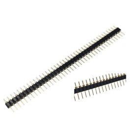
40 Pin Male 2.54mm Single Row Pin Header Break away Round Pin Gold Plated
Get It Fast - Same Day Shipping
 www.taydaelectronics.com