jdduffield
Active member
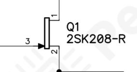
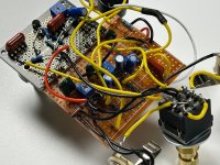
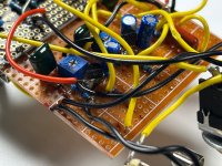
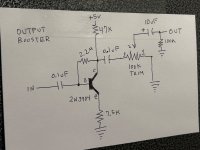
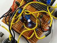
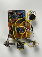
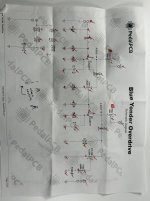
I am attempting to build a Blue Yonder from the schematic. For Q1 and Q2, I’m using 2SK30A JFETs. I’ve noticed it is working, but quieter when the pedal is engaged in comparison to it being bypassed. Is there a resistor value I can swap to affect output volume?
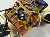
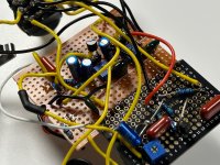
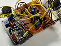
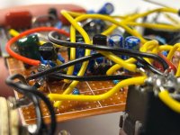
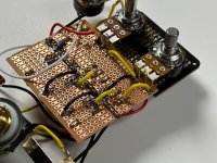
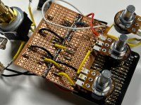
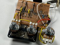
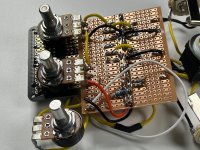
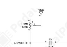
Also, leg 1 of these trim pots go to ground, right? (See photo)
Also, leg 1 of these trim pots go to ground, right? (See photo)
Attachments
Last edited: