Breadboarding A Fuzzy Fox - Spectacular Failure!

Ginsly

Well-known member
Although I can build PPCB projects, vero, and perfboard, I kind of skipped over translating a schematic to breadboard. I've successfully followed along with @BuddytheReow's excellent Executive tutorial and one for a silicon Fuzz Face, but some of the fundamentals that would allow me to breadboard other circuits still haven't clicked yet. The Fuzzy Fox is a bit more complicated than those, and honestly, I'm still not even sure how to set up the diode and capacitor in the power section alone! Yeesh.

@BuddytheReow , any chance you'll be breadboardin' this in the future..? :) Seeing people do a few different circuit setups will help things click, because for now, some of this is still quite confusing. I tried to reference the power section setup in the Exec tutorial, but it's different enough from the FTM that I still wasn't sure what to do. Then there's the entire circuit to contend with... I went left to right on the breadboard along with the schematic, but I'm obviously making some fatal mistakes and misunderstanding a lot of this.

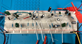
Embarrassing as it is, I posted a pic of my comical attempt to breadboard this. I just left the power diode and electro off since I'm using a battery. I realize the jacks, pots, and switch aren't shown, but they're plugged in too.
Screen Shot 2024-05-12 at 10.01.37 AM.png
Screen Shot 2024-05-12 at 10.09.21 AM.png
 
Last edited:
Are D1 and 4 backwards?…
Very possible! I set them up with both cathodes connecting to the negative side of C4 since that's what it seemed to indicate in the schematic... Apologies, it's hard to see which electro is C4 and C3 in the breadboard photo, but D1 and D4 are connected to "-" on C4. I'm 100% certain I'm translating things incorrectly from schematic to breadboard...
 
Very possible! I set them up with both cathodes connecting to the negative side of C4 since that's what it seemed to indicate in the schematic... Apologies, it's hard to see which electro is C4 and C3 in the breadboard photo, but D1 and D4 are connected to "-" on C4. I'm 100% certain I'm translating things incorrectly from schematic to breadboard...
Ok, that’s as it should be. Time for a probe. I usually use my output jumper and just go back and trace the signal…
 
Ok, that’s as it should be. Time for a probe. I usually use my output jumper and just go back and trace the signal…
Gotcha. Anything else jump out as obviously wrong? I have the feeling I'm just misinterpreting when things are supposed to connect directly (same breadboard row) and when things are connected via other components (say, a resistor between two points).

I've also never probed a circuit! Ha... I'm that new. I'll give it a shot, going from right to left like you mentioned...
 
Use your probe to check the collectors of each transistor to see where the dead signal is. Then I would confirm your connections on the breadboard. Sometimes it’s just one component that needs a light tap and the whole thing will fire up. From there, if it’s still not working, I would then check the voltages on the base and collector pins. Base needs about 0.7V to open the gate in the transistor.
 
Use your probe to check the collectors of each transistor to see where the dead signal is. Then I would confirm your connections on the breadboard. Sometimes it’s just one component that needs a light tap and the whole thing will fire up. From there, if it’s still not working, I would then check the voltages on the base and collector pins. Base needs about 0.7V to open the gate in the transistor.
Thanks @BuddytheReow! I have the feeling it's more than a loose connection - there are likely several critical errors here! Ha... I haven't probe traced before, nor have I measured transistor voltages. Yep. I have a long ways to go. I'll figure out how to do that and start there.

IF you wind up doing one of your immensely helpful breadboard walkthroughs on the Fuzzy Fox I'm happy to send a bunch of snazzy transistor labels I made!

(of course I'll send ya some either way if you like!) ;)
 
Last edited:
Gotcha. Anything else jump out as obviously wrong? I have the feeling I'm just misinterpreting when things are supposed to connect directly (same breadboard row) and when things are connected via other components (say, a resistor between two points).

I've also never probed a circuit! Ha... I'm that new. I'll give it a shot, going from right to left like you mentioned...
From what I glanced over, nothing popped out. You’re really the only one that will be able to tell for sure, so we’ll have to help you figure it out.


There is a lot at the above link. As for the probe, you can definitely follow the instructions in that link. Since you used a breadboard, however, you already have a probe. Hook everything up (guitar, breadboard circuit, amp, tube socks) and then take wire connecting your output to the amp out from the breadboard; in this case, whatever you have on Lug 2 on the volume pot. Next, use that as your probe, and strum your guitar with one hand while touching the probe to the component legs in the signal path.

Follow the yellow line, more or less (I’m many beers into the evening at this point)…

IMG_4155.jpeg
 
From what I glanced over, nothing popped out.
I really appreciate you taking a look. You can't see the jacks and pots, but it seems like they should be connected properly... hmm
Since you used a breadboard, however, you already have a probe.
Ahhh ok. Whenever I see people mentioning this, I just assumed it was using a multimeter to confirm continuity - seems like it's a bit more complicated than that. Thanks for the link! Good to know that the breadboard is already kind of set up to do this easily.

Sometimes there's a "huh, I did everything right and it's not working!" scenario, but this isn't one of them! Ha... I would bet money I'm just interpreting some paths incorrectly or something... I'm a visual artist, and I think sometimes I perceive diagrams like schematics in a weird way. Hard to explain! I'll get it eventually, and this is definitely trickier than breadboarding a Fuzz Face... Thanks for the tips, I really appreciate it.
 
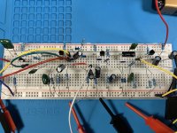
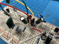
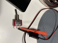
Ok I'm getting somewhere! I repopulated the board, and the fuzz works! But.... no octave, and the octave switch does nothing. I've clearly set it up incorrectly. I could really use some help identifying what I did wrong... Here's a new pic of the breadboard, and the switch is connected near the middle with the yellow and red jumpers - I also did a close-up of that section. If I take the switch jumpers out completely it seems to make no difference either. I'm so close! @Coda and @BuddytheReow any tips to help me get to the finish line? 🏃‍♂️
IMG_1787.jpg
IMG_1788.jpg
IMG_1789.jpg
 
Take a look at the diodes and the way they are oriented. A good way to read the schematic for diodes is the the arrow/triangle is pointing to the cathode. GE diodes, for some reason, have the little stripe on them backwards (the anode side). In other words, both signal paths will hit the cathode of the diode. I think you may need to flip them both around.
 
...Hook everything up (guitar, breadboard circuit, amp, tube socks) ...

There. I think you found the problem. Ginsley's been working on the breadboard wearing tube-socks, but... well, now he must be wearing transistor-socks 'cause he's got fuzz, but... no octave.

Knee-high transistor-socks, and if that doesn't work, try wearing some full leggings, but NOT chaps...
No, not ready for chaps yet.


Ginsley, when you've sorted out this circuit, here's some more breadboard layouts to explore:

http://breadboardguitarfx.blogspot.fr/

Beavis has some, too.


I think you're already getting the hang of it, though.


One thing of note: when breadboarding it's easy to mix up resistor values, plugging unplugging replugging.

Especially if you put in a 390k instead of a 390Ω, then the circuit won't work at all — no need to ask me how I know...
 
Take a look at the diodes and the way they are oriented. A good way to read the schematic for diodes is the the arrow/triangle is pointing to the cathode. GE diodes, for some reason, have the little stripe on them backwards (the anode side). In other words, both signal paths will hit the cathode of the diode. I think you may need to flip them both around.
I actually used BAT41s instead of Ge diodes, so I think they’re oriented correctly..? I have the feeling I didn’t set them up correctly in relation to the switch, though…
 
Should something be connected to the third prong of the switch maybe..? I’m struggling to see where I went wrong with the Octave/Switch…
 
Should something be connected to the third prong of the switch maybe..? I’m struggling to see where I went wrong with the Octave/Switch…
You should be using the middle lug and one of the outer ones. The third one is unconnected…
 
You should be using the middle lug and one of the outer ones. The third one is unconnected…
Yep, that’s how I connected it... bottom pic in the last ones I posted.

Rats! Any possible culprits here? I’m lost! 🤷‍♂️
 
Solved. I moved the negative side of C3 down to one of the empty, bottom rows of the breadboard along with R9-to-ground. Moved one of the switch jumpers down there too. Boom- ear-piercing octave!

The switch wasn’t doing anything before because it was all bunched up in the same upper row. I was about to fall asleep just now and it dawned on me!

So take note- do NOT listen to your body when it needs rest; instead, go monkey around with wires. 🐒
 
Glad you got it working! Troubleshooting breadboards can be a real pain. I’m also a stickler for using only half my breadboard unless I have to. Like regular troubleshooting, you just need to walk away for a while and it will suddenly dawn on you
 
Glad you got it working! Troubleshooting breadboards can be a real pain. I’m also a stickler for using only half my breadboard unless I have to. Like regular troubleshooting, you just need to walk away for a while and it will suddenly dawn on you
Thanks man! A lightbulb kind of turned on, and I’m pretty psyched that I was able to fix it.

I’m still not exactly sure how I would set up the power section if I included it in my breadboard instead of just plugging in the battery snaps. I’d love if someone could explain that!
 
Back
Top