MBFX
Well-known member
Good afternoon, everyone! I have built 10 PedalPCB projects so far, and I decided to start trying out my own circuits and modifications on breadboard. Solderable breadboard seemed like a great way to begin going from breadboard to permanent installation, and I got some 1/4 size Electrocookie solderable breadboards for a few dollars on Amazon and got started.
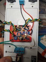
My first build, a Fuzz Face, was rotated 90° because I am a fool and it didn't work. My second build, another Fuzz Face, worked first try! I socketed the transistors, used a trimpot for a bias resistor, and had hours of fun playing with my creation. My third build, an LPB-1, should have been a breeze! However, I wired it all up on the Electrocookie breadboard, connected it to my PedalPCB auditorium, and it didn't work.
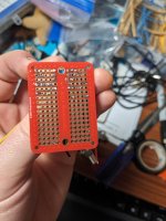
I assume there are three problems: first, I don't have power rails on my solderable breadboards, and so I have to make my own and be really good at following the schematic and making sure what is on the breadboard is the same as on the solderable board. Second, I am trying to use as little space as possible so I can build another circuit on the same board using this circuit as a first gain stage, and I am probably misdirecting current somewhere. Third, I still don't REALLY understand what is happening in the circuit, so I am probably missing something obvious.
Here is the schematic I am using for the LPB-1 build:

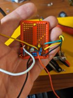
And here is how I have translated that to the solderless breadboard:

Can anyone see an obvious problem with my circuit? I spent hours looking at it, reading about signal flow to make sure the schematic wasn't wrong, examined my soldered circuit to see if it matched my drawing, and I can't figure it out! There are some components sharing holes for the sake of compactness - is that a problem?
My first build, a Fuzz Face, was rotated 90° because I am a fool and it didn't work. My second build, another Fuzz Face, worked first try! I socketed the transistors, used a trimpot for a bias resistor, and had hours of fun playing with my creation. My third build, an LPB-1, should have been a breeze! However, I wired it all up on the Electrocookie breadboard, connected it to my PedalPCB auditorium, and it didn't work.
I assume there are three problems: first, I don't have power rails on my solderable breadboards, and so I have to make my own and be really good at following the schematic and making sure what is on the breadboard is the same as on the solderable board. Second, I am trying to use as little space as possible so I can build another circuit on the same board using this circuit as a first gain stage, and I am probably misdirecting current somewhere. Third, I still don't REALLY understand what is happening in the circuit, so I am probably missing something obvious.
Here is the schematic I am using for the LPB-1 build:
And here is how I have translated that to the solderless breadboard:
Can anyone see an obvious problem with my circuit? I spent hours looking at it, reading about signal flow to make sure the schematic wasn't wrong, examined my soldered circuit to see if it matched my drawing, and I can't figure it out! There are some components sharing holes for the sake of compactness - is that a problem?


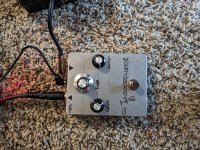
 I should have just enough room left on the board to comfortably fit a Fuzz Face with transistor sockets and a bias trimpot, and then I'll stick the whole thing in a 125B. Next step is to remove the yellow output wire, since the LPB-1 will cascade directly into the Fuzz Face.