Building Flock Fuzz - tips for soldering rotary switch breakout board?

FleeRemi

Member
Hey all

Currently building the Flock Harmonizing Fuzz, and i'm a bit nervous about getting this rotary switch soldered in correctly. A few (potentially dumb) questions: Do i want the breakout board flush with the main pcb? If it isn't supposed to be flush, will i need to solder both sides of the pins on the 10-pin line to ensure a good connection? I got the "10 pin stackable" from Tayda, hope I got the right type of leads/pins.

Sorry, still new to a lot of this.

As always, thanks in advance for any possible help!
 
Last edited:
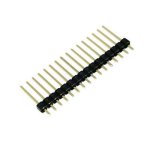
I don't think that stackable one will work easily.
You want this type
1725137501760.jpeg
2.54mm spacing
You can get them from mouser, digi, Amazon, Ali...
Handy to have so buy a pack of 50+
You can snip them into short lengths easily.
Now, how to:
I haven't built this but this is how I would.

Dry fit your pots into the enclosure and solder pcb into place.
Place the short end of the pin headers into the pcb. Make sure the plastic spacer is flush to the PCB.
Fit the rotary, attached to PCB, onto the headers and put its nut on.
Solder the header pins onto the rotary PCB.
Remove PCBs from enclosure and solder the main PCB side of the rotary switch pins. Ensure that everything is angled properly. You can just solder one at each end(pin 1 and 10) and do a quick fitment check. Solder the rest, trim, noise.

Now, if you get long enough headers, you can omit the spacer, slide it to the far end of the pins, mount everything and slode the pins in. The spacer would be the highest point. Solder a couple points on the main PCB, holding the spacer up off the switch PCB(a couple of gator clips would work), then once the main PCB is done, remove/trim the spacer off or solder the switch side and then trim(depending on how much room you have to work with).
Hope that helps.
 
I don't think that stackable one will work easily.
You want this type
View attachment 81202
2.54mm spacing
You can get them from mouser, digi, Amazon, Ali...
Handy to have so buy a pack of 50+
You can snip them into short lengths easily.
Now, how to:
I haven't built this but this is how I would.

Dry fit your pots into the enclosure and solder pcb into place.
Place the short end of the pin headers into the pcb. Make sure the plastic spacer is flush to the PCB.
Fit the rotary, attached to PCB, onto the headers and put its nut on.
Solder the header pins onto the rotary PCB.
Remove PCBs from enclosure and solder the main PCB side of the rotary switch pins. Ensure that everything is angled properly. You can just solder one at each end(pin 1 and 10) and do a quick fitment check. Solder the rest, trim, noise.

Now, if you get long enough headers, you can omit the spacer, slide it to the far end of the pins, mount everything and slode the pins in. The spacer would be the highest point. Solder a couple points on the main PCB, holding the spacer up off the switch PCB(a couple of gator clips would work), then once the main PCB is done, remove/trim the spacer off or solder the switch side and then trim(depending on how much room you have to work with).
Hope that helps.
Dang alright i just ordered some from amazon, coming in 2 days! Really appreciate this write out
 
Back
Top