Can’t have a foot switch.

Mad Max

New member
New member here.
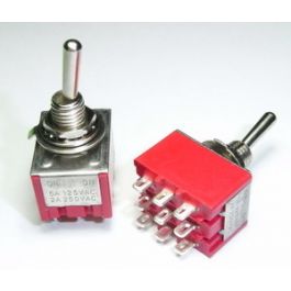
If this has been addressed elsewhere please direct me to it. I want to build my first pedal, probably a Golden Fleece. But the typical footswitch requires too much pressure for my intended application. I’ve been building cigar box guitars and I want to include a single knob effect inside of the guitar body. I’d need to switch it on and off with my hand (not my foot!) Has anyone replaced the foot switch with a toggle switch? Any advice on the appropriate switch and wiring (or warnings not to attempt because…) would be appreciated.
If that doesn’t seem plausible does anyone know of a really light action foot switch?
 
Or a soft click stomp switch ? I know I ordered some black ones that click without too much pressure.
 
no need for the third pole honestly– with a toggle switch you dont need an LED indicator since the direction of the switch already gives a visual and tactile indication. My preference for toggle based effects is these chunky bois. I use em for any tabletop pedals i make (for lap steel and keyboards) and I dig em for onboard guitar stuff too:
 
You're right, on the guitar, I won't need the LED. So looking at the Copper Clad Fuzz schematic, I assume I can just dispense with the short leg that has a 4k7 resistor. LED, and switch to ground in series, right?
 
If you want to have some fun, install it with a relay switch hooked up to an arcade button (with LED so you know when it's on and for a mini-lightshow while you tap it on/off during a solo...)
 
Having built a few CBGs myself, just mind the thread length of the toggle/switch and the thickness of the top of the box.
 
Yeah that's already a challenge. This box is almost 3/8" thick. It's a really nice, white "My Father's Cigars" box which I'm using gold hardware on. I already have a long shaft 500k volume pot on the way. Now I'm looking for a long B100k for the fuzz (which I will likely mount remote from the board). The toggle and LED won't fit the thickness anywhere. In order to preserve the aesthetics of the front, I'm probably going to cut an opening in the top (the short side adjacent to the neck) and use some kind of trim plate for switch and LED.
I actually agree with Bricksnbeatles that the LED is superfluous, and I would rather not have it at all. But this is my first attempt at a circuit board project and it's not clear to me how to modify the circuit to delete it and use a DPDT on-on switch instead.
If anyone cares to talk me through that, I'm happy to try. Also, since the guitar has a volume pot, either the signal IN or the signal OUT won't be directly to or from a jack so I'll have to sort that out. If it were a pedal, the volume would come before the circuit, but I wonder if there might be a benefit to putting the volume after the fuzz. Then you should have full strength pickup signal to the fuzz, color to taste and then control the volume level post-effect. BUT I keep hearing that as a pedal, the guitar volume can clean or dirty things up. Maybe that's more important when your other knob is on the floor!
I appreciate anyone who takes the time to respond to a noob like me!
 
If you are using the Cooper Clad PedalPCB board, all you have to do is use the wiring schematic and omit the middle row of lugs. A control plate is a good option, or you can use a forstner bit to thin the top enough to pass the toggle through (I have done both). I would say have both a volume for the fuzz and the guitar, that way you can control the volume out of the fuzz, but also change the character of the fuzz by altering how much of the pup volume is going into it. Also be aware that the type of pickup you are using (piezo vs standard mag) will affect the fuzz.
 
I will be using the copper clad pcb when it arrives. So just omit the middle row of the foot switch pin diagram huh? I can handle that. And no problem not installing an LED or its resistor, right? The guitar has a humbucker. I’m leaning towards running the pickup straight to the pcb and the pcb output to the volume pot. Looks like I will have to put the fuzz pot through the trim plate as well as I have had zero luck finding a long bushing B100k pot.
 
That’s it. The LED is just an indicator light. You will want to place the switch in between the pup and board unless you want all fuzz all the time. You might want to consider a 3pdt toggle anyways so you can cut power to the fuzz when not in use not that a fuzz is going to drain a battery that fast, but……
 
Okay, I've just built the circuit on the pcb. I need to mount the pot remotely though. I know the center potentiometer hole in the pcb should be for the pot wiper. But which one of the pcb holes is the ground (the one with the square around it is my gut instinct)?
Also, I've had no luck finding a B100k pot with long bushing so any thoughts on the effect of using a A250k pot?
 
The pots are soldered to the back/solder side of the pcb, body of the pot oriented towards the top of the board so you can just match up your lugs that way, or yes, the square would be lug 1 to ground. A (logarithmic) taper is usually preferred for volume. Subbing a 250 may mess with the usable sweep. If you have a 250k ohm (or close to like say a 220k) resistor, you can solder that across lugs 1 and 3 to make a 125k pot
 
Last edited:
Awesome input Diynot! I will parallel a resistor to get closer to the 100k. I did wire in the LED and resistor and used the 3PDT toggle switch recommended by Nic. I just didn't want to make too many changes to the layout on my first build. Fingers crossed, I'll let ya know soon.
 
Back
Top