SOLVED cetus preamp - no signal when engaged

maertz13

Member
Hey all, first post, first build. i've done some much simpler circuits and mods, but this is the first big one.

i have good bypass, but as soon as i turn on the pedal, it mutes. LED comes on. volume is up. cables are good. i have reflowed every connection, checked the orientation of every polarized part, swapped the jacks around to ensure i am plugging in correctly, and at this point i am out of my depth. the only suspicions i have are that i have a bad component somewhere (i've read that there are bad batches of op amps), or that there is an error in the build doc that i'm unaware of. i found a picture of someone else's build and they've got the zener diode at D2 flipped. a backwards diode would certainly stop a signal dead in it's tracks.

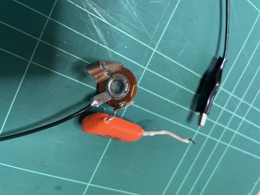
i'm open to any ideas and any criticism at this point. i know my soldering is a little sloppy. reflowing a couple dozen components in a magnifying glass has made a flux mess. bad vision, shaky hands. there's a reason i don't do this for a living :D. also attached is a picture of the (much cleaner) build that was being sold on reverb (so it's safe to say it works) with that diode flipped
 

Attachments

  • IMG_5082.jpeg
    IMG_5082.jpeg
    582 KB · Views: 52
  • IMG_5083.jpeg
    IMG_5083.jpeg
    547.7 KB · Views: 52
  • IMG_5084.jpeg
    IMG_5084.jpeg
    525.4 KB · Views: 53
  • Screen Shot 2023-05-14 at 3.38.27 PM.png
    Screen Shot 2023-05-14 at 3.38.27 PM.png
    348.6 KB · Views: 51
If it’s built correctly the board will work. I agree with what’s been said workmanship is the number 1 problem with the board not working. Try to limit the amount of heat you’re applying! 2-3 sec tops. You got this, trust in yourself and double check all your components before committing to soldering them in place.
 
1. Measure the voltages on the ICs.
2. Use the audio probe.

Let's stop guessing based on photos, now it's time for your action. But not for looking at the board and reflowing the solder. Measurements and probe. It's the only proper way of troubleshoothing here.
All I’ve got is a multimeter. And I wouldn’t begin to know where to start with that.
 
All I’ve got is a multimeter. And I wouldn’t begin to know where to start with that.
alright then, here's my AUDIO PROBE 101:

preface:
IME (i've made a lot of errors), more often than not, pedal issues are usually overlooked build error(s) .....and sometimes poor solder joints, or dirty boards.
the killer with pedals is, some errors can be very difficult to locate / identify.
this is where audio probes save the day.
you can look at a wiring/build layout for days and still not see the key point that's been missed / misplaced.

an audio probe will at least give you a reasonably pinpointed clue about where you've messed up on the circuit.

if there is any advice i can give, go and make yourself an audio probe setup:
1652075679571.png


here's mine:
976352-2a9fabd53b38bdf66d276fe29e370ee8.jpg


all you need is:
- mono jack (plugin a cable, send to an amp / stereo)
- insulated wire+alligator clip (to clip to ground)
- 100nF cap (voltage rating to your application, i used 630V cos the leads are robust and can use on HV amp circuits too)
- audio source to feed the pedal input (guitar, music player, iphone, whatever.. you might need adaptors)

what to do:
- feed some constant audio into the input of the pedal circuit being tested (iphone, mp3 player, whatever, use an adaptor etc.)
- with the tip of the probe (capacitor lead), you trace the signal from input, along specific points of the circuit board (schematic will help here) until you find where the signal is being lost/muted/weird.

- eg. start with the 3PDT switch, make sure the board is actually getting the input signal (with the switch in 'on' position, of course). then before and after the 10nf input cap, then the 68k resistor, (this goes to the TL072 input buffer), then check output pin of the TL072 buffer, the 2n2 cap, etc. and just keep following the audio signal pathway as can be seen on the schematic.

- you could also start from the output jack and work backwards,
eg. output jack tip -> switch --> 1uF cap --> 47R etc..


here’s me trying find where i made an error on an OD-1 build: (yes, my desk is horrendous)
d8471c49-b2d2-4539-9d03-3b09c61047c7-jpeg.1018888
 
Last edited:
I got a Cetus that is working fine (in my opinion :)). I'll post the voltages, hope it helps. Anything else you want me to measure let me know.

All pots at 12 o'clock, cables connected.

IC100

7.62 3.81 0 -3.58 -7.28 3.05 3.11 7.63

IC1

0 0 0 -7.29 0 0 0 7.63

IC2

0 0 0 -7.29 0 0 0 7.63
 
got the materials and made the audio probe. fantastic piece of kit.

signal at input, signal through C1, R1, and nothing on any pin of the first op amp.

i mentioned that i bought enough parts to build 2 of these. so i built the second one, taking a lot of advice here and assembled it with SURGICAL precision. yeah... that one doesn't work either. audio probe gets signal at pin 3 of the first op amp, and then nothing anywhere else.
 

Attachments

  • IMG_5105.jpeg
    IMG_5105.jpeg
    586.7 KB · Views: 9
  • IMG_5106.jpeg
    IMG_5106.jpeg
    539.7 KB · Views: 9
  • IMG_5111.jpeg
    IMG_5111.jpeg
    332.8 KB · Views: 9
IC2
-.08 to -.1 at pin 4
-.15 at pin 6
-.17 at pin 7
-.36 at pin 8

IC1
-.08 to -.1 at pin 4
-.36 at pin 8

IC100
-.36 at pin 1
-.3 at pin 2
-.08 at pin 4
-.1 at pin 5
-.21 at pin 6
-.02 at pin 7
-.1 at pin 8

R100
-.36
 
you know, all of this looked fishy so i tried a different power supply
.....MAN do i feel like a jackass. totally works. literally the first step in troubleshooting... start at the end and the beginning. is it plugged in? is a fuse blown? are YOU plugged in?
 
so build #2 works as expected. noisy, but that might have a lot to do with it being not in a case. build #1 works... kinda. but there's a really obnoxious noise coming through. suppose I'll try the audio probe on that one again tomorrow. i'm willing to accept that after the constant reworking i very likely torched something. learning experience, i guess. it was probably fine after the first correction, i just had the wrong power supply
 
so build #2 works as expected. noisy, but that might have a lot to do with it being not in a case. build #1 works... kinda. but there's a really obnoxious noise coming through. suppose I'll try the audio probe on that one again tomorrow. i'm willing to accept that after the constant reworking i very likely torched something. learning experience, i guess. it was probably fine after the first correction, i just had the wrong power supply
Great job with sticking with it! Years ago, with my first few builds (before I discovered the helpful online forums) several landed up in the trash before I understood the basic and systematic troubleshooting approaches.

And yes, the Cetus is a noisy circuit, especially with the gain past noon. Just the nature of being a high gain circuit.
 
the sea terror lives! i've got sound, all my controls work, and finally all that time i spent on paint paid off. the noise persists. it's not like a gainy amp hiss, it is a constant kind of square wave drone. the noise is affected by the tone controls as well as the gain, so it's a safe bet that something is happening between the input and the op-amps, right?

IMG_5112.jpeg
 
I'd also rule out and equipment around that may have interference... fluorescent light etc etc ... When I have my pedalboard plugged into my scarlett solo and type on my keyboard I can hear electrical interference when I type..lol
 
1. Measure the voltages on the ICs.
2. Use the audio probe.

Let's stop guessing based on photos, now it's time for your action. But not for looking at the board and reflowing the solder. Measurements and probe. It's the only proper way of troubleshoothing here.
Is there a way to like this 100x?
 
I'd also rule out and equipment around that may have interference... fluorescent light etc etc ... When I have my pedalboard plugged into my scarlett solo and type on my keyboard I can hear electrical interference when I type..lol
i surprisingly CAN rule that out, as i know my apartment to be very noisy and the first thing my guitar hits is an ISP hum extractor + decimator. with the pedal disengaged and a butt ton of gain on my amp instead, nearly silent.
 
i'm getting -10 and 10 at pins 4 and 8 of IC1. based on micmac"s measurements, that's too high. no reason to write them all down, the readings at every leg of all 3 IC's is too high. 10v at R100 too. just measured the power adaptor i have. it's kicking out 10.4 (headdesk)
 
i'm getting -10 and 10 at pins 4 and 8 of IC1. based on micmac"s measurements, that's too high. no reason to write them all down, the readings at every leg of all 3 IC's is too high. 10v at R100 too. just measured the power adaptor i have. it's kicking out 10.4 (headdesk)
Ok, so what power supply ARE you using?
 
Back
Top