You are using an out of date browser. It may not display this or other websites correctly.
You should upgrade or use an alternative browser.
You should upgrade or use an alternative browser.
Charge pump board
- Thread starter Danny
- Start date
Chuck D. Bones
Circuit Wizard
I have not seen a PedalPCB board that requires a Charge Pump board. I bought some for doing custom builds and mods. Why are you using one?

Robert
Reverse Engineer
IN/GND/SW/OUT interface directly with the 4 pads at the bottom of most PedalPCB boards.
IN pad on the top left corner of the board (and the corresponding ground pad beside it) go to your Input jack.
OUT pad on the top right corner of the board (and the corresponding ground pad beside it) go to your Output jack.
+/- pads on the top left of the board go to your DC jack.
From there, it depends on the circuit and how you plan to use the board. For the most typical installation you would connect the +/- pads on the top right of the board to the +/- pads of your main effect PCB. Then the mini slide switch on the right would select between 9V / 18V operation.
You'll need to determine if they effect you're using it with can handle (and would benefit from) 18V.
The "Fixed" pads at the bottom are for direct unswitched access to the supply voltages.
Some examples:
If you don't plan to use the voltage selector switch (and want to always power your effect on 18V) you would use the Fixed +18V pad at the bottom.
If you need -9V (for positive ground effects) you would use the Fixed -9V pad at the bottom.
If you have a circuit that requires 9V and 18V supplies you would use the Fixed +9V and Fixed +18V pads at the bottom.
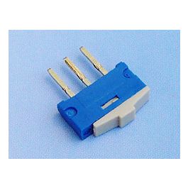
This is the slide switch that fits the pads:
 www.taydaelectronics.com
Alternatively you could wire the pads to an external toggle switch.
IN pad on the top left corner of the board (and the corresponding ground pad beside it) go to your Input jack.
OUT pad on the top right corner of the board (and the corresponding ground pad beside it) go to your Output jack.
+/- pads on the top left of the board go to your DC jack.
From there, it depends on the circuit and how you plan to use the board. For the most typical installation you would connect the +/- pads on the top right of the board to the +/- pads of your main effect PCB. Then the mini slide switch on the right would select between 9V / 18V operation.
You'll need to determine if they effect you're using it with can handle (and would benefit from) 18V.
The "Fixed" pads at the bottom are for direct unswitched access to the supply voltages.
Some examples:
If you don't plan to use the voltage selector switch (and want to always power your effect on 18V) you would use the Fixed +18V pad at the bottom.
If you need -9V (for positive ground effects) you would use the Fixed -9V pad at the bottom.
If you have a circuit that requires 9V and 18V supplies you would use the Fixed +9V and Fixed +18V pads at the bottom.
This is the slide switch that fits the pads:
Mini Slide Switch 1P2T Through Hole 0.2A 24VDC
EXCEL CELL ELECTRONIC - Get It Fast - Same Day Shipping
www.taydaelectronics.com
Alternatively you could wire the pads to an external toggle switch.
Veepedaldude
New member
I plan on trying it with a stockable drive
UnusedPortion
Member
I just built a Glory Hole Overdrive pedal, and it sounds good but I find that unity gain is at ~2 o'clock on the Volume control. I'm thinking it might benefit from adding the charge pump board (perhaps JHS would agree, since I believe the Morning Glory v4 added 18V operation). Do you think that would be a good solution? I assume the other components can handle 18V (all my caps are rated for at least 50V). Any concerns?
Chuck D. Bones
Circuit Wizard
No concerns, but...
With 9V power you should be getting at least 5Vp-p at the output with all three controls maxed. Maybe something is wrong with your build. If so, increasing the power supply voltage won't help. Check the drain voltage on Q1.
With 9V power you should be getting at least 5Vp-p at the output with all three controls maxed. Maybe something is wrong with your build. If so, increasing the power supply voltage won't help. Check the drain voltage on Q1.
UnusedPortion
Member
Thanks, Chuck. I am getting 6.9V on the drain of Q1. How can I measure the output voltage you mentioned?
Chuck D. Bones
Circuit Wizard
Got an oscilloscope?
Q1's drain voltage is a little high, but not that far off. You should be getting 3.4Vp-p. What do you have in the chain after this pedal?
Q1's drain voltage is a little high, but not that far off. You should be getting 3.4Vp-p. What do you have in the chain after this pedal?
UnusedPortion
Member
Thanks, Chuck. I went back and checked my work, and I figured out the problem. I had flipped the 47n and 47p capacitors (yikes). Once I fixed that, the pedal is performing as expected. Thanks for your help!
Chuck D. Bones
Circuit Wizard
Yup, that would do it. Glad you got it fixed. Check all the other parts while you're in there.
sodapop808
New member
Would it just be a SPDT on/on if you want to run a toggle?IN/GND/SW/OUT interface directly with the 4 pads at the bottom of most PedalPCB boards.
IN pad on the top left corner of the board (and the corresponding ground pad beside it) go to your Input jack.
OUT pad on the top right corner of the board (and the corresponding ground pad beside it) go to your Output jack.
+/- pads on the top left of the board go to your DC jack.
From there, it depends on the circuit and how you plan to use the board. For the most typical installation you would connect the +/- pads on the top right of the board to the +/- pads of your main effect PCB. Then the mini slide switch on the right would select between 9V / 18V operation.
You'll need to determine if they effect you're using it with can handle (and would benefit from) 18V.
The "Fixed" pads at the bottom are for direct unswitched access to the supply voltages.
Some examples:
If you don't plan to use the voltage selector switch (and want to always power your effect on 18V) you would use the Fixed +18V pad at the bottom.
If you need -9V (for positive ground effects) you would use the Fixed -9V pad at the bottom.
If you have a circuit that requires 9V and 18V supplies you would use the Fixed +9V and Fixed +18V pads at the bottom.
This is the slide switch that fits the pads:
Mini Slide Switch 1P2T Through Hole 0.2A 24VDC
EXCEL CELL ELECTRONIC - Get It Fast - Same Day Shipping
Alternatively you could wire the pads to an external toggle switch.
Chuck D. Bones
Circuit Wizard
Yes.