circuit snippets

Audandash

Well-known member
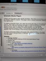
So I was wondering how to do circuit snippets? I know there is supposed to be a way how but I have no clue. What I mean is there are certain things that I use on a lot of circuits that would be a lot easier not to have to build each time. For example the power section or my off board wiring. At the moment I just open a previous circuit, copy that area then paste it in the new one. It saves time but it's not very efficient because I have to open and close other circuits since I can only have one circuit up at a time. I think I saw a plug in for it but no explanation on how it worked.

Thanks in advance
 
Last edited:
Some software has that functionality built in. I believe the new version of DipTrace does something along those lines.
I keep a folder of the blocks that I use regularly in individual schematic files.

Any time I need them I can just copy / paste everything (or just the parts I need) into a new schematic.

 
So essentially build it just like symbol (KiCad terms) and place it like a part. That would probably work.

I have this plug in installed but have never seen where the plugin actually is. It doesn’t load in the top bar like all the other plugins I have installed and I can’t find it in the menus either.
 

Attachments

  • IMG_5496.jpeg
    IMG_5496.jpeg
    921.3 KB · Views: 7
I finally found it but the it only shows on the pcb layout side not the schematic side. It also doesn’t pop up a box like it’s supposed to. I read about it on the guys GitHub and it may not support newer versions of KiCad.
 
Last edited:
Disclaimer: I have not read this yet, but....

I think this is what you are looking for, and I was wrong, it was KiCad that got this feature in Version 9, not DipTrace.

Unless I'm mistaken this is now a native feature and doesn't require an add-on / plug-in.


Please, someone give KiCad a checkbox to disable automatic connections so I can use it. Please!?! :ROFLMAO:

I wonder if ChatGPT could do it for me... :unsure:
 
So essentially build it just like symbol (KiCad terms) and place it like a part. That would probably work.

I have this plug in installed but have never seen where the plugin actually is. It doesn’t load in the top bar like all the other plugins I have installed and I can’t find it in the menus either.
With Kicad 9, Schematic Editor, go to View > Panels > Design Blocks.

Just be sure to save your blocks to a global custom library

See: https://docs.kicad.org/9.0/ca/eeschema/eeschema.html#schematic-design-blocks
 
Please, someone give KiCad a checkbox to disable automatic connections so I can use it. Please!?! :ROFLMAO:

I wonder if ChatGPT could do it for me... :unsure:

"I want to suggest a new feature:
Make a bug report that explains your feature as well as possible. Highlight the benefits you think this feature will bring to all users.
Mark your bug as a feature request by adding the wishlist tag"

"The easiest way to report an issue with the KiCad application is to select Help → Report Bug"

 
Also, it's pretty easy to create user templates. (to use them you do File -> New Project From Template).
I think you can have schematic as well as PCB templates. I only use the PCB templates.
( I have all of my offboard / power sections as 'Design Blocks' which have already been mentioned )

It's pretty convenient to create some standard board sizes. I have three boards on my template
and choose which one based on the size/knobs of the device. One for 3/4 knob layout,
one for 5/6 knob layouts that is as wide as the inside of a 125B, and I just created one for a
50x50mm (max size "cheapest" 4-layer board @ jlcpcb). On these templates I have the edge cuts
plus measurements, guide lines, and centering circles on a user layer to align pots, switches,
etc to the "standard" enclosure drillings.

Once I've decided which one to use, I delete the other outlines and I can hide the user layer with
measurements once the placements are done.

@Robert - what do you mean by automatic connections? The only thing I can think of
right off is automatic connection between global labels / power flags? Or maybe the
aggressive snapping traces to pads when routing?
I need to figure this out. Right now i have edited a 125b foot print that has knob placements etc. i i place it temporarily so i can have my pots in the correct place. It also helps me draw the board within the correct dimensions. In eagle i had the hole board pre done based on pots. Already had my power and i/o lines run as well. It was great. I never figured out how to do it in kicad. I had seen the templates but never really dug into how to set it up. Guess i need too as i have been using it for a few years now snd that would be super convenient. How do you create the initial templates? I have seen where you can pull from templates but didn’t know how to create the actual template.
 
How do you create the initial templates?

It was a while ago that I set it up, but from what I remember it was really simple.
I created a templates directory, then created a project in there like I would create
any other project. Then you add a directory called 'meta' and put an "info.html" file
in there just with the description. Anything you've added to the template gets copied
into a new project you create when using that template. Remember to go to
'user templates', there are system level ones, too. There's probably a step
to tell it where to look for your template directory.

(You can add icons, too, but I didn't)

I mostly followed this:


My info.html is just:

Code:
<!DOCTYPE HTML PUBLIC "-//W3C//DTD HTML 4.0 Transitional//EN">
<HTML>
<HEAD>
<META HTTP-EQUIV="CONTENT-TYPE" CONTENT="text/html;
charset=windows-1252">
<TITLE>125B Pedal Template</TITLE>
</HEAD>
<BODY LANG="fr-FR" DIR="LTR">
<P>Initial pedal outline templates to fit a 125B enclosure.
Set up for 'PedalPCB Stanard' potentiometer/switch layouts,
offset either 16.5 or 20.3mm from center, 25.4mm apart
vertically.
</BODY>
 
Back
Top