SOLVED Circulator no effects working

Zac Fact

New member
Hi,
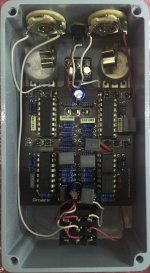
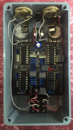
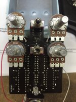
I’ve recently built 2 of these pedals in tandem (after waiting nearly 2 months for them to arrive) & are getting no effects; only a very thin & weak sound.
No matter where I set the pot values it makes no difference to the sound.
Except for some strange reason the Sweep seems to act like a volume control.
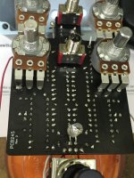
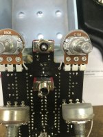
I followed the diagram from attached PDF & the printed values on the circuit board.
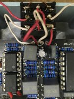
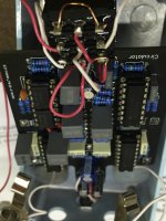
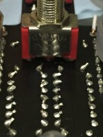
I rechecked all the values & solder joints & everything else that could be a problem
It seems to be a design problem not a build problem as the same thing is happening on both builds.
I already built the Delegate, The Ocelot & Seabed Delay from you without any problems. They work great.
But I could be a lot happier if these pedals worked.
I had a look at the forums & there seems to be no consistency with the issues at hand.
I also noted that many had no issues at all with the build.
I just want the pedal to work as intended without any major mods.
Any advice would be much appreciated.
Just to recap all the problems:
• Low volume,
▪ Thin sound
▪ Pots not responding (except sweep acting as volume)
▪ Works in bypass no problems.
▪ Led comes on when effect is engaged but does not pulse to the rate

Cheers :)
 

Attachments

  • Circulator.png
    Circulator.png
    387.7 KB · Views: 20

Can we see more pics of the underside of the board? It sounds like you may have some bad soldering.
 
Hi Buddy I have taken everything apart several times
• I checked all the solder joints & continuity between all components based on the circuit diagram with the multi-meter.
• I can confirm that every component is making contact with the board & not shorting out & there are no dry solder joints.

• Remember I built 2 of these at the same time so any issues mentioned above would not have been replicated exactly on the 2nd build.
I’m not a newbie to electronics. I have been doing this line of work for many many years.
• I can see the user Chuck D Bones had the same issues & modded the board.
• Its becoming clearer that there seems to be a design issue.
• The question I ask is if these issues were known to exist then why wasn’t any amendment updates included within the documentation build? It would have saved me a lot of time & frustration.
• I can see that there are various mods on the forums but outside of personal tastes (re pot values), which ones would you consider to be the “unofficial boneyard editions” to get this thing going?
• I appreciate how much work everyone here within this community contributes. If it wasn’t for your efforts, I wouldn’t be enjoying the pedal effects I have now.

Cheers
 

Attachments

  • IMG_6883.JPG
    IMG_6883.JPG
    1.1 MB · Views: 19
  • IMG_6882.JPG
    IMG_6882.JPG
    867.3 KB · Views: 17
  • IMG_6881.JPG
    IMG_6881.JPG
    982.2 KB · Views: 17
  • IMG_6879.JPG
    IMG_6879.JPG
    524.1 KB · Views: 14
  • IMG_6866.JPG
    IMG_6866.JPG
    1.1 MB · Views: 16
  • IMG_6865.JPG
    IMG_6865.JPG
    1.1 MB · Views: 18
Perhaps it's a part that's common to both builds causing your problems

Where did you get your LM13700s and is the bi colour LED common anode

Now I'm not au fait with LM13700 VCOs which I think this is, but I do know in similar LFO circuits the LED is part of the circuit

If yours is not flashing in time with the rate control it may indicate the oscillator section isn't working

Your first pic is out of focus and difficult to see colour bandings and some cap values, could you post a well lit in focus pic so we can give it the once over

I've built many pedals checked and re checked and still missed an incorrect value or wiring fault it's very easy to do especially if you're frustrated, maybe someone will spot something
 
Last edited:
I have heard that the Grand Orbiter is not as lush / deep as some of the phasers. The mods that Chuck came up with all seem like good ideas to me. They had mentioned a Boneyard edition of this pcb but no idea when it will be out. It sounds like this build is not the easiest which is unfortunate since it is pretty high on my list.
 
• Its becoming clearer that there seems to be a design issue.
• The question I ask is if these issues were known to exist then why wasn’t any amendment updates included within the documentation build? It would have saved me a lot of time & frustration.

I feel fairly confident if an issue were known, it would have been corrected and/or documented. :)

I do hope you get the pedals working. (y)
 
Last edited:
Hi peoples,

I’ve pulled this thing apart so many times its starting to look shabby now.
That led was a UV which I replaced with a standard Red & it made no difference.
Plus I replaced the TL0’s & that made no difference.
And I replaced the LM13700n in the area you suggested & still no difference.
Even though the signal is weak I can hear the rate change when I tweak the pots
Its not a Cap or resistor issue (Ive uploaded a clearer image for your perusal) & definitely not a board issue (apologies for that).
I suspect that its the IC Chip. I bought mine from Tayda. Has anyone else had issues with the same chip?
Any recommendations? I was look at the Texas instrument Model: ICSN0033. Has anyone used this one?

Cheers
Zac
 

Attachments

  • IMG_6859a copy.jpg
    IMG_6859a copy.jpg
    323.9 KB · Views: 11
Hi peoples,

I’ve pulled this thing apart so many times its starting to look shabby now.
That led was a UV which I replaced with a standard Red & it made no difference.
Plus I replaced the TL0’s & that made no difference.
And I replaced the LM13700n in the area you suggested & still no difference.
Even though the signal is weak I can hear the rate change when I tweak the pots
Its not a Cap or resistor issue (Ive uploaded a clearer image for your perusal) & definitely not a board issue (apologies for that).
I suspect that its the IC Chip. I bought mine from Tayda. Has anyone else had issues with the same chip?
Any recommendations? I was look at the Texas instrument Model: ICSN0033. Has anyone used this one?

Cheers
Zac
What colours are R24 - 8K2 ???
Very Dark Picture, Very Hard to make out, It looks like Grey, Red, Black, Black, Brown = 820 r
 
Still finding it difficult to see but R29 doesn't look like a 100K?

Can't see R's 3, 21, 22, 30, 34, 102

Here's a clearer pic 100R not 100K that'd give you incorrect voltage from the voltage divider R28 and 29

Now I was looking initially at a different rev build doc so was confused you didn't have a bi colour LED, downloaded the single LED version doc to make sure and R29 is defo 100K

20211119_131559_copy_270x213.jpg
 
Last edited:
Still finding it difficult to see but R29 doesn't look like a 100K?

Can't see R's 3, 21, 22, 30, 34, 102

Here's a clearer pic 100R not 100K that'd give you a fraction of the voltage from the voltage divider R28 and 29

Now I was looking initially at a different rev build doc so was confused you didn't have a bi colour LED, downloaded the single LED version doc to make sure and R29 is defo 100K

View attachment 18882
Looks like 100r for sure! R29 - 100K
Here's a Resistor Calculator to TEST the rest!
Click on Bands for 5 Colours :

Should be100K, not 100 r.jpg
 
Back
Top