Clapton Mid Boost BUT inside the guitar

ac30irons

Member
Dear all, need a bit of help if anyone can assist.

I am thinking of putting the Clapton boost inside a guitar with a dpdt mini switch for true bypass. I know that this how the thing was originally thought of minus the bypass.

A couple of things i do know :-

I would have to put a 50k resistor in place of the volume on the pcb.

The boost would simply replace a tone pot.

I would have to run the ground of the battery snap to a stereo jack.

Why I don’t know :-

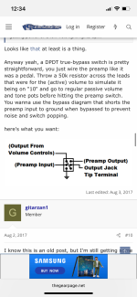
How to wire the whole bloody thing up with dpdt and regular guitar wiring ! The idea is that it comes after pups so the guitars volume remains passive.

I am sure people have done this with fuzz and other boosts but I am clueless how to wire it.

Thanks in advance.
 
I’m surprised no one has released an all SMT version of this circuit. Especially Fender! Lol. They would sell a ton of them if they were a commercial product, and diy’ers would also be all over them (I know I’d build a few myself)
 
I’m surprised no one has released an all SMT version of this circuit. Especially Fender! Lol. They would sell a ton of them if they were a commercial product, and diy’ers would also be all over them (I know I’d build a few myself)
Agreed, the foot print would be tiny
 
I would opt to not lose the tone pot but sounded like @ac30irons planned to delete it. Wasn't sure if they had considered going the push/pull route
Especially in a strat. Even if it was a high $$ model, pickguards are cheap, and there’s a lot of room to install a toggle
 
I have seen this but it looks a bit simple. In essence the boost stands alone and comes after ‘the regular’ controls so would not have to meddle with them.

IMG_8074.png
 
Last edited:
Yep, looks correct.
I'm not certain about the 50k on the volume. I think you would just want to jumper 2 and 3.
Screenshot_20240218-102708-771~2.png
You may not really even need the switch. If you turn the boost pot all the way down, it should just be the buffered signal. Since you won't be killing power to the pcb with the switch, may as well utilize the buffer that's already there and eating battery.
 
Yep, looks correct.
I'm not certain about the 50k on the volume. I think you would just want to jumper 2 and 3.
View attachment 68799
You may not really even need the switch. If you turn the boost pot all the way down, it should just be the buffered signal. Since you won't be killing power to the pcb with the switch, may as well utilize the buffer that's already there and eating battery.
Would the jumper give me fixed full volume up ? Also would I have to send 1 to ground ?

I defiantly want the option of bypassing the circuit.
 
Would the jumper give me fixed full volume up ? Also would I have to send 1 to ground ?

I defiantly want the option of bypassing the circuit.
1 is already tied to ground via pcb.
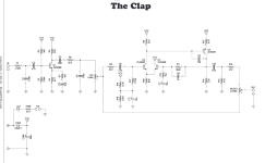
The boost pot is kind of a "clean blend" between the "clean" input buffer signal and the "boost" signal.

On the buffer side, both of the filter are outside of the guitar freq spectrum(that 330p is a weird choice) so there should be little to no to e shaping happening there.
Have you built this yet in pedal form?
If so, I'd try turning the boost to full off and match the volume to the bypass signal. I'm going to bet there is little difference aside from maybe a rouch more high end when engaged as the buffer unloads the cable/pickups some.
Could also possibly change the boost pot to 500k for a bit more isolation.

Now, I don't know how much harmonic content is produced in this circuit if you send full signal into the boost portion. You may want a trimmer to bleed some signal to ground(pin 1) as a set and forget control.
Hey there, I have built it in pedal form. With boost at 0 and volume at 10 it’s a touch louder and also a touch darker !
 
Or, wire it with the switch but don't drill the hole yet. Turn the boost all the way down and toggle the switch.
I think in the on position you may find you like the sound better. An onboard buffer is a good thing :) It shouldn't sound different, just clearer and more articulate in the top end.


Anyone get why the 330p in C is 330p? That going to filter out some radio frequencies but that's it.
Calculator says 17nf gives you a ~20k corner freq.
 
Hey there, I have built it in pedal form. With boost at 0 and volume at 10 it’s a touch louder and also a touch darker !
That's interesting. Kind of surprised because the LPF at the input is WAY high(1026kHz!)
Wonder if it's an output impedance thing.
What if you level match the bypass signal with the volume pot, for science?
 
That's interesting. Kind of surprised because the LPF at the input is WAY high(1026kHz!)
Wonder if it's an output impedance thing.
What if you level match the bypass signal with the volume pot, for science?
I really don’t understand all the complexities of capacitors and what they do 🤦🏼‍♂️ I just know it sounds awesome.

The available pcbs are exact as fender do them so who knows why what’s what ??? I do know that the original from fender ran into a 1meg master volume control on the guitar. Maybe a 50k trim pot in the way to go then ?
 
Yep, looks correct.
I'm not certain about the 50k on the volume. I think you would just want to jumper 2 and 3.
View attachment 68799
You may not really even need the switch. If you turn the boost pot all the way down, it should just be the buffered signal. Since you won't be killing power to the pcb with the switch, may as well utilize the buffer that's already there and eating battery.
@Chuck D. Bones with the volume at max and boost at 0, is the output impedance basically following the Q1 collector output and the reactance of C4?
Wondering if impimenting a 1M to ground somewhere near the output would be beneficial since there is no load at all on the output as this circuit usually was followed by a pot.
That would explain this:
Hey there, I have built it in pedal form. With boost at 0 and volume at 10 it’s a touch louder and also a touch darker !
I wouldn't expect any "darkening" of the tone from the buffer setup alone.

Edit, schem in post 13
 
Back
Top