SOLVED Cobalt Drive problems…..SOLVED……..FINALLY!

Jeff C

Active member
New member here and also new to building pedals, as you will shortly see. I previously built a BYOC Reverb pedal kit successfully and it sounds great. I’ve also built from scratch a Strat, a Tele, a 59 LP, and an LP Junior. So, I wanted a blues driver pedal and thought I’d take a whack at the Cobalt Drive from PedalPCB. The directions are not as detailed as in a kit so I’ve had some difficulty. Clearly in over my head. I managed to procure the parts from the list (not without trial and error on my part) from Tayda. I mistakenly bought a switch without solder lugs so after consulting a patient, helpful friend, bought a daughter board and did my best to figure out how to marry the two - having no skills whatsoever in electronics. History major. I have managed to assemble it but I get nothing from it except static pops when I plug it in. Bypass doesn’t work. No idea what I’ve done wrong but I suspect it revolves around needing to do more with the daughter board on the switch. But what do I know? Here’s a couple of pics (the power jack is not there but I did connect it to test). And I haven’t installed the LED yet. Any and all suggestions are eagerly welcomed. You may recomemd I should just start over but I hope not….. Thank you!
855EE297-D464-47F8-880D-F0D8B9C40E15.jpeg 15E06C0D-93DB-4AE9-944D-BA1BED3416FB.jpeg
 
Last edited:
The audio path is as follows: Q1 is the first gain stage, and I think Q3 is part of the same gain stage, in a configuration similar to a differential op amp, i.e., it forms a negative feedback loop by taking the output voltage and presenting it back to the input via the resistor and capacitor net containing the gain pot. I think that adds more gain, plus the filtering in the feedback net affects the tone of this stage. Then the signal flows into Q5 which is another gain stage (a common emitter stage). Then you have another filtering net and the 4 diodes provide hard clipping, much like a Rat.
Edit: there is a very good article describing the differential configuration here.
 
Last edited:
And to be clear: none of the analysis above is relevant to the issue you are experiencing with the pedal! You should still get signal at the places I pointed out.
 
Do you get signal at any of the pins on Q1? You should have signal on all. If that’s not working, triple check the values of resistors R4 and R6 and also make sure that you have continuity between R2 and the gate of Q1. Once you are done with those tests get back to us and we will take it from there!
 
Do you get signal at any of the pins on Q1? You should have signal on all. If that’s not working, triple check the values of resistors R4 and R6 and also make sure that you have continuity between R2 and the gate of Q1. Once you are done with those tests get back to us and we will take it from there!
Yes, one pin at Q1 gives a signal. The other two do not. Um, how do I check the value of the resistors? I can get on that tomorrow…….
 
Checking values of resistors already soldered in can skew things since they are linked to other components. You can TRY it with a DMM but your best bet is to look at the color coded rings and decipher that way. Just remember to turn the power off when checking
 
Yes, one pin at Q1 gives a signal. The other two do not. Um, how do I check the value of the resistors? I can get on that tomorrow…….
I assume you have signal on the gate? For R4 and R6 you can actually use your multimeter to measure them because they have nothing in parallel. Where did you source your transistors? Do you have a transistor tester?
 
I assume you have signal on the gate? For R4 and R6 you can actually use your multimeter to measure them because they have nothing in parallel. Where did you source your transistors? Do you have a transistor tester?
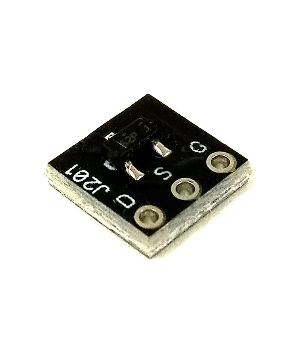
J201’s came from Amazon. Couldn’t find them anywhere else.

Bridgold 10pcs J201 201 N-Channel JEFT Transistor 40V, TO-92​

 
Amazon can be sketchy and JFET are notoriously hard to find in TO-92 format. That may be your problem but you need a transistor tester to verify. Or you can get some from a reputable vendor or use the SMD version which is more commonly available.
 
Back
Top