SOLVED Cobalt Drive problems…..SOLVED……..FINALLY!

Jeff C

Active member
New member here and also new to building pedals, as you will shortly see. I previously built a BYOC Reverb pedal kit successfully and it sounds great. I’ve also built from scratch a Strat, a Tele, a 59 LP, and an LP Junior. So, I wanted a blues driver pedal and thought I’d take a whack at the Cobalt Drive from PedalPCB. The directions are not as detailed as in a kit so I’ve had some difficulty. Clearly in over my head. I managed to procure the parts from the list (not without trial and error on my part) from Tayda. I mistakenly bought a switch without solder lugs so after consulting a patient, helpful friend, bought a daughter board and did my best to figure out how to marry the two - having no skills whatsoever in electronics. History major. I have managed to assemble it but I get nothing from it except static pops when I plug it in. Bypass doesn’t work. No idea what I’ve done wrong but I suspect it revolves around needing to do more with the daughter board on the switch. But what do I know? Here’s a couple of pics (the power jack is not there but I did connect it to test). And I haven’t installed the LED yet. Any and all suggestions are eagerly welcomed. You may recomemd I should just start over but I hope not….. Thank you!
855EE297-D464-47F8-880D-F0D8B9C40E15.jpeg 15E06C0D-93DB-4AE9-944D-BA1BED3416FB.jpeg
 
Last edited:
+1, check out this build report to get an idea.
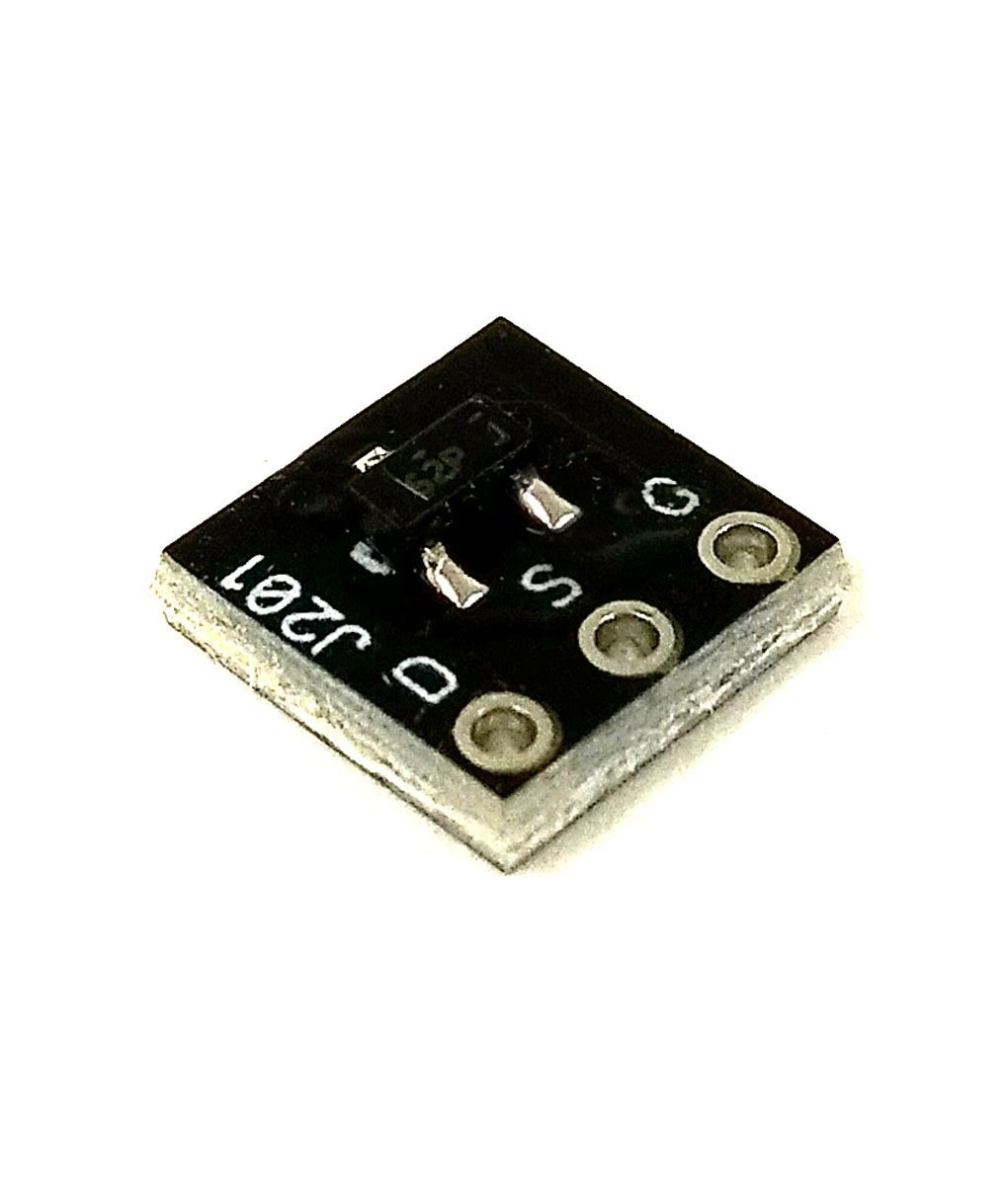
Got the J201’s today. Awesome. I saw from that build report pics, though, that it appears there is another small adaptor that the pins go through before going into the PCB? I guess I can make do without them unless you think they are essential. If so, where would I get those? I don’t see them on the website…….
 
Well, got the new J201’s in. Sadly, same result. Bypass works but with the switch on, I only get audio to the in pad, r1, r4 and Q1 (one of the new J201’s). Nada from there. None of the other components light up. It looks like from the schematic, if so use my multimeter, I should get connectivity from Q1 to Q3, Q5 and r6. I get connectivity to r6, which looks like ground, and Q5. I get connectivity from: C4 to R8; Q5 to R12, a ground, and C7; C7 to R14. Q3 to r8 and C5; C5 to the gain pot, C7 and r10; C7 to r10, q5, r14; q5 to r12;
 
Shoot, not done yet. Q5 also to q1; C7 to r14 and c9; r14 to r17 and c11 and c12; c9 to C7, r16; r16 to d1 and d3; d1 to d2; d2 to d3; c12 to r18; r18 to r17. That’s all so far. Here’s a crude pic. 40A97648-1AB5-45A3-9065-85EC51F5AA6C.jpeg
 
I’ll have to examine the traces tomorrow. I have to confess they look a mess. I’ll try to clean them up with some isopropyl alcohol. For signal, do you mean audio with my probe or just connectivity with the multimeter?
 
I only get audio to the gate pin of Q1. Also, i was incorrect when I said above that Q1 and q5 show multimeter connectivity. It is r4 that connects to the drain pin on Q5.
 
Back
Top