Cobbler Preamp - No output from IC1

PangeaDestructor

Active member
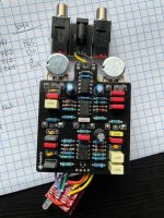
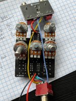
Hey all, got the Cobbler put together and trying to troubleshoot it. No output from the pedal, with the audio probe I'm getting no signal coming from pin 1 of IC1. I wasn't paying attention and somehow dropped an OPA2134 in for IC1, is that a critical error or just a $6 oops?

Voltages are below, something is clearly off. Cheers in advance for any help or suggestions.

IC100
1 8.65 8 8.65
2 5.10 7 5.36
3 0.00 6 3.91
4 3.49 5 8.48

IC1
1 8.15. 8 8.65
2 7.88. 7 8.12
3 7.84. 6 7.87
4 8.32. 5 7.81

IC2
all zeroes except 4 (-8.48) and 5 (8.65)
 

Attachments

  • IMG_0629.jpg
    IMG_0629.jpg
    477.5 KB · Views: 15
  • IMG_0630.jpg
    IMG_0630.jpg
    545.1 KB · Views: 15
Are you sure you're measuring correctly? The voltages at Pin 4 of both IC1 and IC2 should be the same as IC100 Pin 5. Take a look at the schematic in the lower left, and follow the pin numbers of each IC: https://docs.pedalpcb.com/project/Schematic-Cobbler.png
IC100 pin 5 is -8.48, looks like i left out the "-" above, but i just measured everything again and came up with the same numbers as before. Definitely scratching my head on this one. I start at pin 1 top left and go counterclockwise on them.
 
IC100 pin 5 is -8.48, looks like i left out the "-" above, but i just measured everything again and came up with the same numbers as before. Definitely scratching my head on this one. I start at pin 1 top left and go counterclockwise on them.
No other suggestions for now, other than to thoroughly scrub both sides of the board with a toothbrush and isopropyl alcohol, to make sure that there's no hidden solder bridges or stray strands of wire. I hope you get this working, as this is a fantastic pedal - I just built one (on vero) and it's become my go-to for clean/semi-clean tones. It has such a complex and rich tone structure. If I have time later, I'll measure and post my IC pin voltages.
 
No other suggestions for now, other than to thoroughly scrub both sides of the board with a toothbrush and isopropyl alcohol, to make sure that there's no hidden solder bridges or stray strands of wire. I hope you get this working, as this is a fantastic pedal - I just built one (on vero) and it's become my go-to for clean/semi-clean tones. It has such a complex and rich tone structure. If I have time later, I'll measure and post my IC pin voltages.
If I'm not mistaken, you shouldn't be getting any DC voltages on pins 1,2,3 and 5,6,7 on the two opamps.

My voltage readings (with no audio signal, just the 9.2 Volts connected from my power supply):
IC1 and IC2:
1. 0 8. 7.48
2. 0 7. 0
3. 0 6. 0
4. -7 5. 0

IC100:
1. 7.48 8. 7.48
2. 4.31 7. 0
3. 0 6. 2.71
4. -2.94 5. -7.0
 
Ok so something is definitely wrong here. Thanks for this, I've gone over the whole thing again, scrubbed it, saw some things that looked like shorts but weren't once the flux was gone. Stumped. Gonna try again in a bit.
 
I’ll try and check my voltages in a bit here with the ground connected to the ground of the dc jack. Depending on where you’re reading ground you could get all different readings.

But I am worried you just fried the ic by not suing sockets and soldering it directly.
 
I removed the switch and i/o module, plugged it into my testing platform. Still nothing, but here's something interesting - with the volume pot at zero, if I turn it up it pops. like there's a pop right when you start turning it from zero. Weird.
 
Always socket ICs - no matter how skilled you are at building pedals. I think we’ve all learned the hard way. And even if the IC is not the culprit, the act of desoldering and removing it will invariably destroy it (or the board).
 
Last edited:
Ok so ic1 and ic2 all pins other than 4 and 8 are 0v with 4 being -8.63 and 8 being 8.7. Here’s a photo of a working pedal as well for comparison if you like. I used the ring if the input jack for ground reading to measure. Which makes sense as they are half the supply voltage E0C9C5F5-B504-4750-A101-D1C735187E61.jpeg
 
Ok so ic1 and ic2 all pins other than 4 and 8 are 0v with 4 being -8.63 and 8 being 8.7. Here’s a photo of a working pedal as well for comparison if you like. I used the ring if the input jack for ground reading to measure. Which makes sense as they are half the supply voltage View attachment 43279
Thanks again, got sidetracked by stupid work stuff but I'm going to try and pull that IC tonight and replace it with a socket to try some further troubleshooting.
 
I find it strange that your supply is 9.2 but you’re only getting 7.48 at your ic power pins. I’d probably take a look at the schematic follow the power circuit and see where you are losing it. Looks like your a full volt and some change below where dirty boogie and I are. Though it looks like both your 5817 and r100 are the correct parts. If you have an audio probe try and trace the audio signal I would start at your input jack then ic 1 pin 1, if you’ve got it there ic2 pin 1 etc just follow the schematic. When you lose signal back track and see where it’s lost. I might also disconnect power and use the ohm setting on your multimeter to check the resistance of r100. Maybe even try checking the 5817, I had a weird issue with voltage in a recent build and it was a bad diode.
 
I was just thinking I might try and replace that diode as a first step, I have some new 5817s incoming.

With the audio probe I was getting sound going into IC1, but none coming out from pin 1 on that IC.
 
Back
Top