D3LAY- Only dry signal

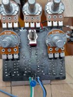
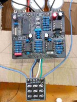
Hey Hive Mind, first FV-1 build done and i am only getting dry signal when effect is active.

-Pots all seem to be working, can probe and get signal (obviously blend pot has no wet signal though)
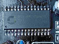
-FV-1 has signal at Pin one, nowhere else. No probable audio at EEPROM pins

Any other thoughts on troubleshooting steps?

Schematic and pics of build below. Thanks in advance!


1618835476223.png


I’d check the dc voltage on the fv-1 pins that are supposed to be at 3.3v.

next, I would ground pin13 of the fv-1. Easiest way is to loop a wire on the leg of the resistor that connects to pin13. This activates the programs that come stock of the fv-1, instead of the ones loaded on the eeprom. Check out the fv-1 datasheet to see what these programs are. If the effects work with pin13 grounded, then you have an issue with the eeprom.

edit: basically same as what pedalpcb recommended at the same time
 
Had a thought this morning. I do have a couple other EEPROMS here for other builds I have yet to start...3Verb, VHS, and Arachnid. I didnt look at the schematics but could i swap out to test? Thoughts?
 
You could put another eeprom in to test, but grounding R5 (the leg that connects to pin13) should be sufficient to tell you somethings up with the fv-1, not the eeprom. Did you check the voltages on pins it’s supposed to be 3.3v?
 
You could put another eeprom in to test, but grounding R5 (the leg that connects to pin13) should be sufficient to tell you somethings up with the fv-1, not the eeprom. Did you check the voltages on pins it’s supposed to be 3.3v?
I have 3.3V at pins 6, 8, 13, 15, 20, 21, 22, 23, 26....NOT 19, which looks like I should from the schematic. Is that right?
 
Pin19 should be ground, not 3.3v. Otherwise I think it looks good. Pin14 and 15 are for communicating with eeprom, I don’t personally know why 15 would be positive but 14 not. but with pin13 grounded, I would think the fv-1 wouldn’t care what’s happening on those pins. You could double check by removing the eeprom, and grounding pin13 again.

otherwise... you have audio at pin1 but not 28. Fv-1 is receiving proper voltages at pos pins, so that’s a tricky one. Could be faulty fv-1 I guess but I don’t know as that’s been a problem for anyone. Other options are bad soldering on fv-1 pins, or the output of pin 28 is being ground somehow (like if C11 was shorting to ground or something). You could check joints around there for continuity to ground.
Thanks again Phil. Just did some poking around C11, and nothing. Double checked solder joints, all looks well.

Should I try to heat up the pins of the FV-1? Maybe flow a little solder on em?

Any other suggestions?

Much appreciated!
 
I have the same problem... took advice to ground the left side of R5 and I could hear the FV1 working with tremolo, chorus, and something else. I'm going to order a new EEPROM and see if that fixes the issue.
 
Most likely it is a soldering issue on the FV-1. The photos you posted are not high enough resolution to really see the soldering. I would definitely try carefully redoing the solder on the chip. From what I have read it seems like a pretty robust chip that can survive quite a lot, so a broken chip seems less likely than soldering
 
From my experience, it is possible to have a solder connection to the EEPROM pins that is good enough to register on a multimeter as a continuous connection, but not good enough for error free digital communication. I had an arachnid that would work from internal sounds but not the EEPROM. The multimeter gave me continuity beeps from the actual FV-1 pins to the actual EEPROM pins. Just would not work. There were shorts to adjacent pins. Reflowed the solder on the fv-1 pins that connect to the EEPROM and it suddenly came to life.
 
I got the replacement EEPROM, but now when the effect is engaged, there is no signal. I will get the voltages later for the FV-1 and post pics later.
 
I went back to the original EEPROM, got signal again, and got the voltages for the FV1:

PinVoltage
63.3
83.3
131.6
141.6
150.425
202.79
212.60
222.88
233.32
263.39

I see that some of the voltages are low; not sure why.

When I use it, there is no wet signal; the volume works fine, the mix when turned all the way to the left turns the volume all the way down, and no sound is heard; the rest of the knobs have no effect.

I've attached some pics. I realize that the FV1 looks a little dirty; I've tried using a flux cleaning pen, and that is as good as I can get it.

Any/all help is appreciated.
 

Attachments

  • full back.jpg
    full back.jpg
    582.7 KB · Views: 13
  • pcb full.jpg
    pcb full.jpg
    444.8 KB · Views: 13
  • FV1.jpg
    FV1.jpg
    341.4 KB · Views: 13
I'm not an expert like the other posters and I've only done one FV-1 build, the BuggFX Daydream. I had a problem that when the toggle was switch was in the bottom position, I would not get any effect and turning the mix knob would kill the sound. I couldn't find anything that was wrong in the build. In my case I replaced the crystal and it fixed everything. Wouldn't hurt to replace that if you have any extra.
 
The photo is not great, but Pins 4-8 on the FV-1 look a bit dodgy. Pin 9-13 look as if they are not soldered. Pin 23 also looks not soldered. There is solder there, but it does not look as if it connect the pin to the pad. Try examining them through a magnifier and resoldering with the magnifier.
 
Back
Top