D9D Diode Forward Voltages

debrad

Active member
I recently purchased a batch of 30 D9D diodes from a Ukrainian seller on eBay and sat down to measure the forward voltages tonight.

What I found appears to be in line with the measurements that @SillyOctpuss posted in this thread (https://forum.pedalpcb.com/threads/diode-forward-voltages.13607/post-153914) for some other D9* diodes but I wanted to know if this sounds reasonable:

Most of the D9D diodes I received were in the 0.2-0.3 V range but some measured as high as 0.59-0.65 V.

Does it make sense that some would measure that high or should it make me suspicious that they may be some other type?
 
Does it make sense that some would measure that high or should it make me suspicious that they may be some other type?
It's too soon to say whether the diodes are suspect. This is because the forward voltage you measure generally depends strongly upon how you measure it - i.e., Vf will increase with the amount of current flowing through it. As a rough rule of thumb, stompboxes will drive currents of ~100µA or so through the diode. But many measuring schemes may run 1-10 mA (or more) through it. There are several threads here on properly measuring diodes - e.g., try https://forum.pedalpcb.com/threads/measuring-forward-voltage-of-diodes.3460/ and listen to experienced folks like @Chuck D. Bones .
 
There also are some threads here on measured V-I curves for various diodes, e.g., see https://forum.pedalpcb.com/threads/measured-odd-and-common-diodes-iv-curves.19777/. Looking at them may help make my comments above clearer.

Just keep in mind that for a given part number, there will still be a fair amount of variance between different devices - they will vary due to different manufacturers, slight difference in processing, etc, etc. This is generally true for most semiconductor devices - e.g., diodes, transistors, FETs, etc.
 
Thanks @darwin999, I really appreciate you taking the time to respond.

I understand the complications that arise from measurement methods and it's important to keep that in mind but maybe a little outside the scope of my question. In my case, I measured everything with the same device so, regardless of what current my DMM is using, it used the same current for all of the diodes I tested. MOST of the D9D diodes I purchased have a forward voltage around 0.25V while a limited few are around 0.58V. Those in the 0.25V range appear to align with what I've seen for other D9* types and the others are more than double that.

With that said, your second response is more closely related to what I'm trying to figure out: is it reasonable to expect to see that kind of variation in the forward voltages of a batch of the same type of diode?
 
Has anyone ever gotten bored or interested enough to put a resistor in series with diodes under test and also collect the determine the diode current (If) along with Vf?

I'll avoid my bad habit of rambling incessantly and just suggest I think you will find the combination of both parameters may give another dimension of behavior, at least where the diode is well into the conducting range. Where the Vf is no longer increasing much, If will.

I am late to this diode party, and this may have already been discussed to death, but any diode datasheet curves reveal what someone said earlier, that Vf varies a lot, and can exceed significantly exceed the nominal, expected or 'textbook' voltage.

This especially true with more (OT) complex devices like optoisolators or 'couplers, where the current thru the photodiode is more important than the voltage.

Above, if not obvious, I'm implying you measure the DC voltage across the series current sampling resistor (call it 'Rs') with one DMM, and the Vf of the diode under test with either a 2nd DMM, or you move your probes in the case of a single DMM. The diode current is then V(Rs)/Rs.

I guess I did ramble.

Murray
 
Last edited:
  • Like
Reactions: spi
Has anyone ever gotten bored or interested enough to put a resistor in series with diodes under test and also collect the determine the diode current (If) along with Vf?

I'll avoid my bad habit of rambling incessantly and just suggest I think you will find the combination of both parameters may give another dimension of behavior, at least where the diode is well into the conducting range. Where the Vf is no longer increasing much, If will.

I am late to this diode party, and this may have already been discussed to death, but any diode datasheet curves reveal what someone said earlier, that Vf varies a lot, and can exceed significantly exceed the nominal, expected or 'textbook' voltage.

This especially true with more (OT) complex devices like optoisolators or 'couplers, where the current thru the photodiode is more important than the voltage.

Above, if not obvious, I'm implying you measure the DC voltage across the series current sampling resistor (call it 'Rs') with one DMM, and the Vf of the diode under test with either a 2nd DMM, or you move your probes in the case of a single DMM. The diode current is then V(Rs)/Rs.

I guess I did ramble.

Murray
I think this may be utilized (with additional sophistication) in SMU (source measurement unit) diode parameter testing methods. I have run out of fancy vocabulary...if it interests you, there is information online, and you won't need an expensive automated tester to read the theory and extract some ideas.

I might as well put ALL my off-topic trivia in one post...someone brought up the mojo term.

I was studying for an electrical engineering class, and it was putting me to sleep. For some reason I don't remember, I had chosen to study in a library in the music college...maybe to take a break and read something more interesting. I found a journal on African-American ethnomusicology (don't remember what it was, it was long ago, maybe 1995). An article said that the origin of the word mojo was African voodoo that ended up in Haiti, and referred to a voodoo fetiche, or talisman, and that the pronunciation of voodoo became hoodoo in some American music. Jimmy Smith (I don't know who first used the phrase) singing about how he "got his mojo working, but it just don't work on you", was about a voodoo fetiche. They didn't have those in my neighborhood...I was just an ignorant kid in the suburbs.

So it's ironic people want mojo in their gear, that may or may not exist, and may or may not work on somebody. "Hey, man, I don't hear any mojo. Do you?".

Good night.
 
Your diodes are probably fine. Leakage is part of the "mojo" of germanium diodes, and can mess with your measurements. As long as they conduct one direction and not in the other, they're (y)...
 
Has anyone ever gotten bored or interested enough to put a resistor in series with diodes under test and also collect the determine the diode current (If) along with Vf?

I'll avoid my bad habit of rambling incessantly and just suggest I think you will find the combination of both parameters may give another dimension of behavior, at least where the diode is well into the conducting range. Where the Vf is no longer increasing much, If will.

I am late to this diode party, and this may have already been discussed to death, but any diode datasheet curves reveal what someone said earlier, that Vf varies a lot, and can exceed significantly exceed the nominal, expected or 'textbook' voltage.

This especially true with more (OT) complex devices like optoisolators or 'couplers, where the current thru the photodiode is more important than the voltage.

Above, if not obvious, I'm implying you measure the DC voltage across the series current sampling resistor (call it 'Rs') with one DMM, and the Vf of the diode under test with either a 2nd DMM, or you move your probes in the case of a single DMM. The diode current is then V(Rs)/Rs.

I guess I did ramble.

Murray
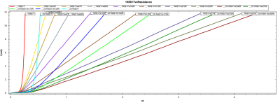
Here is how the behaviour changes, quite a low resistance means drastic changes.. Screenshot 2024-06-28 144109.png
 

Attachments

  • 1N5817vsResistance.pdf
    192.4 KB · Views: 3
Here is how the behaviour changes, quite a low resistance means drastic changes..View attachment 77645
Compared to the miniscule resistance of the diode itself, when forward biased, that small resistance added is very large. So, it's limiting current to a much larger degree than the diode by itself would. That extrapolates the IVf curve of the diode over a greater area.

Ohms law and all that. Should/do see a rough doubling of Vf with a doubling of R. Since we're working in ohms here, the small resistance of the leads and testing device in addition to our diode not being ideal, will make it not perfectly double.
Could be interesting to try a 500ohm pot/trimmer in series to hard clippers and try to "tune" the clipping a bit.
 
Back
Top