Deflector Reverb Pedal - Will this solder burn to the PCB make my pedal not work? URGENT

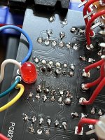
I built a PedalPCB Deflector Reverb pedal for my electronics project in school and it is due tomorrow and need to know if this solder burn has ruined my pedal for the good. I also think that the issue may be my soldering tactics for the potentiometers, but I can't tell. It is a Deflector Pedal PCB and when I turn the pedal on the guitar can run through it perfectly fine and two of the potentiometers make some weird noise but there is definitely no reverb and the circuit isn't working. Basically, when everything is plugged in, the light turns on when I press the switch and the guitar signal runs through the circuit because I can hear the guitar in the amp. The 25K potentiometers make a ringing noise that has no effect on the guitar signal itself, but every other potentiometer does absolutely nothing. There is basically no effect when I run turn the switch on except for the signal gets a little bit louder. IMG_0460.jpg
 

Attachments

  • IMG_0449.jpg
    IMG_0449.jpg
    1.2 MB · Views: 50
  • IMG_0453.jpg
    IMG_0453.jpg
    1.7 MB · Views: 47
  • IMG_0461.jpg
    IMG_0461.jpg
    1.4 MB · Views: 40
  • IMG_0454.jpg
    IMG_0454.jpg
    1.2 MB · Views: 44
I don’t see anything that I can say for sure is ruined on the pcb, but I would definitely suggest reflowing a lot of those joints to clean them up. Make sure there’s good contact and no bridging.

I’m guessing the ringing only occurs on one of the 25k pots (density or dilute (called mix in the schem))? Or is it really both? Density is part of the clock circuit with controls the cycle rate of the fv-1 chip. The dilute (mix) when it’s down mutes the reverb signal out of the fv-1, and when it’s up should increase the volume of the reverb. More info here might give more clues.

I didn’t see any parts or wires I could say for sure were the wrong part or installed wrong, but double check all the cap values. For example, I see a ceramic disk cap for a 100nF, which I think is uncommon to use disk for that value.

Tips for next time - use a socket for ICs, especially the eeprom (IC3). Using pots with legs to mount to the pcb makes for much less wiring.

After checking these things and reflowing joints, the next step would be using an audio probe (they’re simple to wire up or even use alligator clips, just google) and a multi-meter to check for the correct voltage at certain points, especially of the fv-1. The fv-1 datasheet is helpful to learn what voltage should be on what pin.

We learn the most by troubleshooting. Hopefully even if it’s past the deadline your prof will appreciate the effort to troubleshoot.
 
I would say there is a lot of exposed leads, all those wires will tend to cause shorts if you expect to box it up. Also those pots over the board are not isolated (the other 3 are). Make sure nothing is touching something it should not.
 
Back
Top