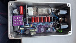
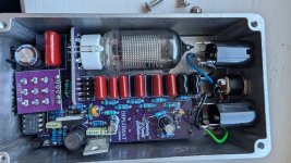
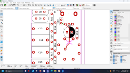
Hi thanks for the reply, this build was a bit of a physical challenge as I am recovering from a serious infection in my hand and arm that kept me in Hospital for 9 days and has left my left hand very weak and with poor sense of touch. My circuit board didn't have and pads/holes for the resistor to the left of the 100uf cap which I think was R21 so to add one I'll have to get creative, It's a different pcb to the build docs, I'll try and work out where to tack in a flying resistor or maybe change the pot . Any clues would be appreciated.If you have a link where R21 470k resistor should be you have increased the output of the pedal by about 30%, R21 limits the output of the signal.
If you add a 22k resistor across leg 1-3 on the volume pot you have also changed the tone of the pedal a lot, you have lost a lot of the low end of the signal.
I think it would be a lot safer for the tube if you install R21 at 470k or even higher if you want to drop the output level, and then you could place a switch across R21 to increase the output level when the switch shorts out R21.
You can use this calculator to see what changing the volume pot to less then 22k will do to the signal, CG is the capacitor you select with the rotary switch (390pF - 47nF) and RV is the volume pot 1000k or 22k if you add the 22k resistor across it. The "Control % Resistance" is where the volume pot is set and I just leave it set at 100%, and "Output Impedance" is the impedance of the tube output but it is not crucial in this case so I would leave it alone as well in this case (unless you really want to work it out just for fun).
I could be wrong but that is what I think is happening in this case.
Cheers
Mick
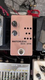
PS....a picture of your pedal would be nice to see as well.
thanks
Neil