DIY All Tube Pedal

TucsonSean

Active member
Hello Everyone,

So, I didn't know if I am putting this in the right location but if not, please let me know where it needs to be moved to.

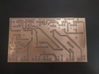
I have been working on a various different preamp pedals for the last several years and I have finally moved forward on one design that I have been kicking around since I built a couple of Particle Accelerator pedals and modified a Mofeta to sound like a Plexi. I have just finished milling one of the PCBs and am working on milling the final PCB. Next steps will be to build up the boards and mill the enclosure.

For a teaser, here is the mock-up of the pedal I did in Solidworks so I can mill the enclosure. It is a little larger of a design using a Hammond 1456FE1 enclosure but I think it warrants it. I will be adding to this build report as I complete more of design. And yes to confirm, it is an all tube Plexi pedal using three 12AX7 tubes. No power amp since I use an HX Stomp XL for my cab sims for my rig. I'm hoping this will give the best of both worlds: feel and sound of tubes with convenience of cab sims and effects. I don't want to give too much away on this since I haven't seen another design like it yet but as soon as I verify the complete design, I will share the full schematic.

-Sean


1771525519774.png
 
Noted. Thank you.

MOD: can you move this to the proper forum?


Pic of the PCB fresh off the mill. Hoping to fully populate it tomorrow.

A side note: vigilante398, I will be using your HV daughter board to power this prototype. I am still working on my HVPS design and hope to finish it soon. I need a 450Vdc supply capable of supplying 50mA for my next project that is in the works but your HV board should work for this design since I only need 275Vdc for the three 12AX7 tubes.

-Sean
 

Attachments

  • Tube Plexi Pedal PCB.jpg
    Tube Plexi Pedal PCB.jpg
    368.7 KB · Views: 13
Noted. Thank you.

MOD: can you move this to the proper forum?


Pic of the PCB fresh off the mill. Hoping to fully populate it tomorrow.

A side note: vigilante398, I will be using your HV daughter board to power this prototype. I am still working on my HVPS design and hope to finish it soon. I need a 450Vdc supply capable of supplying 50mA for my next project that is in the works but your HV board should work for this design since I only need 275Vdc for the three 12AX7 tubes.

-Sean
Board looks great! Can I ask what machine you're milling with? There aren't a ton of us on here, but I think there are enough CNC users we should probably start a thread for it.

450VDC at 50mA is doable, but not trivial. You're almost definitely getting into flyback territory. The nixie supply is easy to put together and can often get the job done, but as I'm sure you've noticed it definitely has its limitations.
 
I'm using a Taig cnc mill. I can start a new thread for the CNC.

My current design IS a flyback UC3843 based design. The xfmr has been an interesting one. I have a couple of versions using a couple of OTS xfmrs and a couple that are custom wound using EF20/ETD20 and ETD29 cores. Hoping one of the OTS ones works well enough so I don't have to wind so many coils. My first single sided SMPS PCB with an OTS xfmr. Let me know if you see any issues.

1771531235062.png
-Sean
 
I'm using a Taig cnc mill. I can start a new thread for the CNC.

My current design IS a flyback UC3843 based design. The xfmr has been an interesting one. I have a couple of versions using a couple of OTS xfmrs and a couple that are custom wound using EF20/ETD20 and ETD29 cores. Hoping one of the OTS ones works well enough so I don't have to wind so many coils. My first single sided SMPS PCB with an OTS xfmr. Let me know if you see any issues.

View attachment 111728
-Sean
Transformer selection is the worst part of flyback design in my opinion. I'm in the process of revising a design that I did so I can get more current out of it and I'm doing everything I can to avoid changing the transformer because it's an OTS part and I know it works 😆

I'm not a power supply expert, and I will always advise leveraging the "recommended layout" from a datasheet if it's available, but it looks like you hit the most important points like ground pours wherever you can, ground separation with a single net tie point, components in the control path of your controller close to the IC, minimizing trace lengths where possible, etc.

Obviously it's hard to tell from just a screenshot and it looks like you've probably already taken some thought on it, but make sure you have your copper-copper clearance spaced generously to keep your HV lines away from anything it could arc to. Soldermask should never be your main plan for electrical isolation, but it does offer some assistance as a thin dielectric layer, so you need to take extra care when using a milled bare copper board.
 
Wow this is cool!

Is it a preamp as designed to run in an amp's fx loop, or can you use it in front as well?

And is it going be for sale at some point?
 
I realized that I had a keep-out over the HV output for my board. Attached it another pic with the keep-out removed so the HV output section can be seen. Not a whole lot needed which is nice.

-Sean

1771561761419.png
 
joelorigo,

I have designed this as an amp-in-a-box pedal. It is designed to run into a cab sim or clean power amp (tube amp not necessary). My rig is an amp-less one and I used the HX Stomp XL for my cab sim and effects. I wanted the tube feel and sound so that is what I have mainly designed this for. I believe it would need some additional filtering if you were to run it into the front end of an amp but it should be fine into the fx loop. I would need to test it to verify.

As for selling it, I'm unsure if I will put it up for sale or just release the schematic into the wild. Time will tell.

-Sean
 
Back
Top