spi
Well-known member
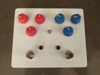
This is the Mach 1 and Southern Belle boxed together into a dual overdrive (1590XX enclosure). M1 is the blue side and SB is the red side. And it has a switch to change the stacking order.
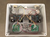
Not an example of the cleanest wiring, because I used extra wire lengths to make all the routing easy.
My initial impressions:
Mach 1 is the most transparent drive I've used. With the gain just over halfway and volume at unity, I can barely tell it's there, except for the slightest hit of grit.
Southern Belle has a lot more gain, with a sweet smooth breakup.
In M1->SB mode, the M1 can goose the SB to get a lot more gain and sustain. And in SB->M1 mode, the M1 boosts the SBs signal for some extra punch.
This was the first time I used the Tayda drilling service, and I'm happy with the way it came out--when doing it myself I usually get some poor alignment because I never get the hand-drill to go exactly where I intended. The time and stress it saved me was worth the fee, given it had 14 holes.


Last edited:


