Dual supply boost with ground loop hum issue

Locrian99

Well-known member
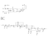
So I started working on this project a while back. And I’m now on my 3rd pcb revision all with the same problem so I’m leaning towards it not being a layout issue. Wondering if anyone sees an issue with my schematic here. Basically its just the frequency interchanger I wanted to run with a dual supply.

Carbon-Boost-page-0001.jpg

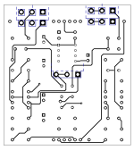
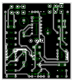
I can post my actual layout later as I’m not at my computer. The hum appears at c5, and you can completely filter it out with the hpf pot.

If anyone sees a glaring issue id’d appreciate it.
 
What kind of hum -- is it low-frequency ~120hz mains type hum, or higher frequency?

How are you testing? I had a hell of a time diagnosing low frequency hum in my pedals,
finding a lot of stuff to be loud post-gain-stages, but I was testing into a battery powered
headphone amp (No earth ground). Once I started testing into something with a proper
earth ground, everything got a lot quieter.

Higher frequency hum might be something with the charge pump (they can be kind of noisy).
 
What kind of hum -- is it low-frequency ~120hz mains type hum, or higher frequency?

How are you testing? I had a hell of a time diagnosing low frequency hum in my pedals,
finding a lot of stuff to be loud post-gain-stages, but I was testing into a battery powered
headphone amp (No earth ground). Once I started testing into something with a proper
earth ground, everything got a lot quieter.

Higher frequency hum might be something with the charge pump (they can be kind of noisy).
I believe it to be classic 60 cycle hum. I didnt run it through a scope however I did use a tuner that shows fequency. With the hpf basically off it was showing 52hz, as turned up the hpf it got quieter but the hz also raised a little I think up to around 58 before it was no longer audible.

Testing i have fully built it and had in an enclosure same issue as having it fully wired up to jacks and switch and just having in’s outs wired into my protoboard. I have tried it on both my bassman 50, and my genz benz black pearl 30 same issue. Different guitars same issue. I thought about just basically jumpering the portion out of the circuit hpf from the output of the lpf to see what that does to at least narrow it down, but I think I kind of already did that by audio probing and finding the issue doesnt show up til the hpf side of c5 (ive also built this 4 times with different parts all 4 exact same issue, with some trace path changes as well.
 
Sorry - does it make noise on your breadboard as well?

One potential source might be oscillation at really high frequency (inaudible, supersonic)
in the gain stage, which then pulls a bunch of current and amplifies ground hum.
That'd track back into the first stage, too, (to C5) since the whole IC might be slammed.
You could try to fix this by putting ~47-100pF between IC2.2 pins 6+7 (in the feedback path)
to pull out any high frequency oscillation -- you could bodge this on the PCB, looks like between
pins 1 and 2 on the gain pot (or of course directly on the IC).

It'd also help to add a decoupling cap (~100n) at the power input of IC2.1. (Which you
could probably also bodge on the PCB).

(edit: also measuring voltage might be interesting - what's VCC and your negative rail measure here?
If it's pulling a bunch of current it's probably dropping quite a bit of voltage over that 100R
in the power filter stage)
 
Last edited:
Sorry - does it make noise on your breadboard as well?

One potential source might be oscillation at really high frequency (inaudible, supersonic)
in the gain stage, which then pulls a bunch of current and amplifies ground hum.
That'd track back into the first stage, too, (to C5) since the whole IC might be slammed.
You could try to fix this by putting ~47-100pF between IC2.2 pins 6+7 (in the feedback path)
to pull out any high frequency oscillation -- you could bodge this on the PCB, looks like between
pins 1 and 2 on the gain pot (or of course directly on the IC).

It'd also help to add a decoupling cap (~100n) at the power input of IC2.1. (Which you
could probably also bodge on the PCB).

(edit: also measuring voltage might be interesting - what's VCC and your negative rail measure here?
If it's pulling a bunch of current it's probably dropping quite a bit of voltage over that 100R
in the power filter stage)
Ill have to check. I remeber there was a fair amount of loss after it on one of my attempts to i just actually jumpered the 100r and it didnt change anything. I actually havent tried the dual supply on the breadboard. Didnt figure it’d change anything from the single supply. Hindsight I can probably toss it back on there. I was hoping i was just missing something obvious :)
 
I can probably toss it back on there

See if you can give the PCB a bodge first w/ those changes and see how it works, before you spend an hour recreating it on a breadboard.
The breadboard might even work fine because it's a breadboard and has built-in capacitors. ;-) If you saw a bunch of loss across
R100, it's kind of suspicious for oscillation (though to be fair I don't remember what the quiescent current of the charge pump
is, which might draw a bit on its own).

edit: and I also just remembered that having the negative rail changes the decoupling story a bit, too. You'll also want a ~100n cap between the negative rail and ground. (so pin4 and pin8 both have a 100n cap bodged to ground)
 
Last edited:
edit: and I also just remembered that having the negative rail changes the decoupling story a bit, too. You'll also want a ~100n cap between the negative rail and ground. (so pin4 and pin8 both have a 100n cap bodged to ground)
i put 100n decoupling caps on both thr negative and positve rails before the ic’s however they are only 1 each rail and are located between them on the layout. Just got home ill post my layout in a bit. But that is in the schematic to the right of the charge pump.
 
Sometimes its only a defective 1044.
Charge pump noise typically is a much higher frequency "whine" in my experience. This has been with a few different charge pumps, not sure if they were from the bunch I purchased from Digikey or Stompboxparts. But none of them in this batch have had issues in any other circuits I've used them in.
 
What happens if you bodge a 47 or 100pF cap across pins 1 and 2 of the gain pot?
(Also the gain pot is right by the charge pump, maybe picking up some noise there).
Ideally you want your decoupling near the op-amp.
You could try bodging a 100nF cap between pins 4 and 8 (+ and - rails) of IC2.

These should both be pretty easy to test.
 
What happens if you bodge a 47 or 100pF cap across pins 1 and 2 of the gain pot?
(Also the gain pot is right by the charge pump, maybe picking up some noise there).
Ideally you want your decoupling near the op-amp.
You could try bodging a 100nF cap between pins 4 and 8 (+ and - rails) of IC2.

These should both be pretty easy to test.
Funny i was actually just reading through your first post. I didn’t have time to try any of those last night hopefully I will tonight. Shouldn’t the decoupling caps be going to ground? I was thinking tacking one on pin 4 to ground and pin 8 to ground. I can try between as well.
 
What happens if you bodge a 47 or 100pF cap across pins 1 and 2 of the gain pot?
(Also the gain pot is right by the charge pump, maybe picking up some noise there).
Ideally you want your decoupling near the op-amp.
You could try bodging a 100nF cap between pins 4 and 8 (+ and - rails) of IC2.

These should both be pretty easy to test.
Tried both no change :( Hmmm maybe i just need to say screw ot ditch the charge pump and just run it off an 18v supply if i want to
 
Back
Top