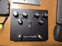
DuoPhase LFO no LFOing

Aentons

Well-known member
All voltages look good but neither of the yellow LEDs are lit. All trimpots set at noon. All the TL072 came from Mouser. Signal is passed in bypass and effect. A weird thing I noticed when putting it together was the led negative pad was square rather than the positive but they are marked with A and K so I checked the schematic to verify and used the letters.

Any ideas what I should check?
1000010960.jpg
 
Last edited:
Do you have any 1054s on hand?
I don't think the 7662 you have in there will deliver enough current
I don't have any others to try.

I have a TC1044SCPA on the A side and a TC7662BCPA on the B side. There is no change when reversing which side the chips are on.
 
Last edited:
All knobs and trimers set to roughly noon. Toggles set to down toward stomps. Looks like IC 2A may have some issues. Here are the voltages using a Onespot.

Edit: I mixed up pins 1-3 on IC1B but it's corrected now

IC1 A. B.
1) 0. 0
2) 0. 0
3) 0. 0
4) -7.79. -7.55
5) 0. 0
6) 0. 0
7) 0. 0
8) 8.96. 8.97

IC2 A. B.
1) 7.74. 0
2) 3.86. 0
3) 0. 0
4) -7.78. -7.55
5) 0. 0
6) 0.8. 0
7) -6.15. 0
8) 8.96. 8.97

IC3. A. B.
1) 0. 0
2) 0. 0
3) 0. 0
4) -7.79. -7.55
5) 0. 0
6) 0. 0
7) 0. 0
8) 8.96. 8.97

IC4. A. B.
1) 0. 0
2) 0. 0
3) 0. 0
4) -7.80. -7.55
5) 0. 0
6) 0. 0
7) 0. 0
8) 8.96. 8.97

IC5. A. B.
1) Var. Var
2) Var. Var
3) Var. Var
4) -7.80. -7.55
5) 0. 0
6) 0. 0
7) 0. 0
8) 8.96. 8.97

IC6 A. B.
1) Var. Var
2) 0. 0
3) Var. Var
4) -7.80. -7.55
5) 0. 0
6) 0. 0
7) Var. Var
8) 8.28. 8.25

IC7. A. B.
1) 8.96. 8.97
2) 5.22. 5.27
3) 0. 0
4) -3.18. -3.10
5) -7.81. -7.55
6) 4.14. 4.15
7) 5.45. 5.52
8) 8.96. 8.97

IC8
1) Var
2) 0
3) 0
4) -7.55
5) Var
6) -6.14
7) -6.14
8) 8.25
 
Last edited:
Here is a closer look at the IC2A area. Sorry about the scars but my edge cutter has developed a bur I need to file down. I don't think of them are deep or severe enough to cut a trace.
1000012032.jpg
 
Last edited:
Back
Top