SOLVED Valhalla , no led, just noise

deadbrent

New member
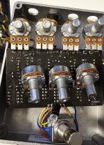
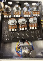
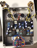
Hi. Valhalla distortion build. Main issue, no led, no output (other than noise). Tried both in and out of enclosure. No bypass just get noise, when 3pdt is turned on the freq of noise changes but no guitar sound. I've tried to troubleshoot with multimeter, tested all resistors and verified components are all in the correct locations. Reflowed solder on all components and checked for bridges (didn't see any). I get continuity and 8.4-8.5V+ power at various points on board/components. Using an on-stage pedal power supply 9v center negative. I tested the led, not burnt I can get it to illuminate via continuity test when placing probes between the a and k pads and by placing probes on the left top 3dpt switch pad (green wire) and pad underneath that (red wire). Any ideas or help would be appreciated. Beginner here so good odds that I have done something silly and not embarrassed to ask, hence this post.. Any help is appreciated. Cheers. 1000016579.jpg 1000016580.jpg 1000016581.jpg
 
Do you have a multimeter? This is a buffered pedal. I would suggest starting at the dc jack and working through the power part of the schematic. Are you comfortable with that?
 
Thanks, not 100% comfortable but will give it a go/google some more info, I did check voltage at various points, including output (8.2v at output lug). Good opportunity to learn to read schematics better. I am seeing around 7.4 -8.2 volts at various points. I'll try a more systematic approach and follow the schamatic.
 
Thanks, not 100% comfortable but will give it a go/google some more info, I did check voltage at various points, including output (8.2v at output lug). Good opportunity to learn to read schematics better. I am seeing around 7.4 -8.2 volts at various points. I'll try a more systematic approach and follow the schamatic.
Great attitude! There are lots of points of voltage reference in the schematics, r100 is leading to the LEDa andOne side of it should be 12v give or take.
 
Im reading 8.4 on the led anode side and the r100. Here ia a rrally basic question anyone know if this pedal should be run at 9v or 12v ....my power supply can do 9 , 12, and 18v
 
The 1044 ic will generate 12v only 9v should be used in powering it
What do you mean by this? I thought you needed a 12v adaptor to power this pedal. Also, on the schematic it says +12v. Am I wrong? A standard 9v pedal plug will work for this pedal? Also, why does the wiring guide show a LM2940 transistor, but the BOM has the L78L12ACZ? Which is it? Super confused here.
 
What do you mean by this? I thought you needed a 12v adaptor to power this pedal. Also, on the schematic it says +12v. Am I wrong? A standard 9v pedal plug will work for this pedal? Also, why does the wiring guide show a LM2940 transistor, but the BOM has the L78L12ACZ? Which is it? Super confused here.
The pedal utilizes a 1044s charge pump here are the schematics. https://ww1.microchip.com/downloads/en/DeviceDoc/21348a.pdf

The transistor questions are best answered by @Robert. They both appear to be voltage limiters and might have slightly different specs but he can answer.
 
Also, why does the wiring guide show a LM2940 transistor, but the BOM has the L78L12ACZ? Which is it? Super confused here.

The wiring diagram is intended to show the wiring, ignore any differences in component values / part numbers you see in that image.

Follow the BOM, and ultimately, what is printed on your PCB.

L78L12 is the correct part number unless you have a much older revision of the PCB.
 
After a lot of tracing and testing found some spots with no voltage. Went over everything again and sure enough I had inadvertantly swapped a 10k resistor with a 10r. Desoldered swapped and it powers up with sound. Only issue now remaining is that the volume is not really working. I'm going to swap out that pot and ...gonna mark this as solved. Thanks to everyone who chimed in. My take aways... check resistor values better and slow down. At least I learned to read schematics better and how to test better. Cheers
 
The wiring diagram is intended to show the wiring, ignore any differences in component values / part numbers you see in that image.

Follow the BOM, and ultimately, what is printed on your PCB.

L78L12 is the correct part number unless you have a much older revision of the PCB.
Thank you. However, I am still not clear on whether I should use 9v or 12v power supply.
 
Back
Top