ElectroVibe Modifications Thread
- Thread starter Big Monk
- Start date

Big Monk
Well-known member
Further investigation of the Electronic Orange manual and the Roger Mayer Voodoo Vibe seems to indicate that the Electronic Orange "Symmetry" control is in fact the Offset we know from the EV. The Bias or Gain control is a trim on the inside like the EV. Also, the Moon Vibe has an internal Volume trimpot, which seems silly as you can just make that resistor bigger in a fixed version.
The RM Voodoo Vibe has a bunch of stuff going on but nothing too crazy. "Symmetry" is again just the Offset control and Bias is external. I'm not sure what is happening with the Speed Range control but I assume it varies the resistors in the speed circuit to expand the range.
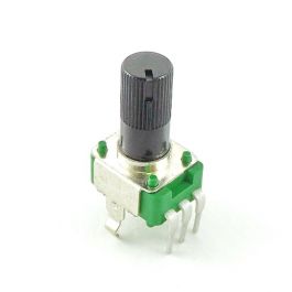
I'm entertaining a small breakout board for use with my EV Mini that will use these pots for external control of Offset and Gain:
 www.taydaelectronics.com
The RM Voodoo Vibe has a bunch of stuff going on but nothing too crazy. "Symmetry" is again just the Offset control and Bias is external. I'm not sure what is happening with the Speed Range control but I assume it varies the resistors in the speed circuit to expand the range.
I'm entertaining a small breakout board for use with my EV Mini that will use these pots for external control of Offset and Gain:
250K OHM Linear Taper Potentiometer Round Knurled Plastic Shaft PCB 9mm
ALPHA - Get It Fast - Same Day Shipping
www.taydaelectronics.com

Big Monk
Well-known member
When Speed footswitch off, Speed 2 knob controls, when on, Speed 1 knob. Is it possible to inverse it? If yes could you please explain?
Cheers
Since the switch goes between the 2 speeds, I wouldn’t think of it as an On/Off switch but rather an On/On.
Any idea how to reverse it? I didn't use the speed mini pcb, directly soldered the cables.Since the switch goes between the 2 speeds, I wouldn’t think of it as an On/Off switch but rather an On/On.
Big Monk
Well-known member
Any idea how to reverse it? I didn't use the speed mini pcb, directly soldered the cables.
Do you mean the LED being on/off?
yes when the speed led off means speed 1 knob active when the led on speed 2 knob active.Do you mean the LED being on/off?
Big Monk
Well-known member
yes when the speed led off means speed 1 knob active when the led on speed 2 knob active.
You could attack this 2 ways:
1.) Simply swap the wire that that comes into the foot switch from the LED to its opposite pole or;
2.) Use a Bi-color LED. I used Red/Blue and have a blue knob on speed 2:

You could attack this 2 ways:
1.) Simply swap the wire that that comes into the foot switch from the LED to its opposite pole or;
2.) Use a Bi-color LED. I used Red/Blue and have a blue knob on speed 2:
View attachment 22567
For the first option, speed led has a continuity on the pin 5. Should I change the opposite pole like below?
Before:
after

Big Monk
Well-known member
For the first option, speed led has a continuity on the pin 5. Should I change the opposite pole like below?
Before:

after
View attachment 22584
Yes.
Big Monk
Well-known member
Has anybody posted what appears to be the choice hfe for the 2N5088 transistors ?
Big Monk you ROCK !
Will you post a photo of the inside of your Electrovibe with all the mods ?
There’s really nothing to see on the inside. Rather, the mods are all on board components with different values or hidden underneath the board.
I wondered this at first too but was told by others that they didn’t check transistors. I just soldered in the first 14 2N5088s I could find and it soundsHas anybody posted what appears to be the choice hfe for the 2N5088 transistors ?
Big Monk you ROCK !
Will you post a photo of the inside of your Electrovibe with all the mods ?

Bricksnbeatles
Member known well
Could you post a little clip of what the phase balance control sounds like?
Big Monk
Well-known member
Could you post a little clip of what the phase balance control sounds like?
I don’t have that mod implemented yet. Was going to go in sometime this week and do it.
Bricksnbeatles
Member known well
Just looked at the schematic— It’s essentially the wet-dry balance in chorus mode though, right? Seems useful— I’d be tempted to put it on my EV build (when I eventually get around to it) if it wasn’t for the fact that it doesn’t fit the aesthetic I’ve laid out for my buildI don’t have that mod implemented yet. Was going to go in sometime this week and do it.
Big Monk
Well-known member
Just looked at the schematic— It’s essentially the wet-dry balance in chorus mode though, right? Seems useful— I’d be tempted to put it on my EV build (when I eventually get around to it) if it wasn’t for the fact that it doesn’t fit the aesthetic I’ve laid out for my build
Yes. The depth of the 2 stages of phasing from the Univibe relies on the frequency cancellation provided by balancing the gains of the wet/dry signals.
At least that’s what R.G. Keen says.