FERAL's imPERFect LAYOUTS

Yes, once breadboarded, you can do whatever you want — in fact, you can do MORE because you're not constrained — for instance you can tinker with a Muff and swap out the tone-stack for a Fender BASS MIDS TREBLE tone-stack far more easily on a breadboard than trying to mock-up the Fender tone-stack on a socketed PCB, which would be a nightmare.

Nonetheless, for me it's easier to swap out component-values on a socketed Muff PCB if that's the only thing I'm messing with — component values — since I'm trying dozens upon dozens of variations from Kit Rae's Web-site.

A Rat PCB, on the other hand — there just aren't as many variations that I'm interested in on a Rat. So it makes no sense to me to socket a Rat PCB, I'd rather just breadboard the Rat variant.

With the socketed EMEXAR, it was worth it to me to devote a PCB to sockets. Variants of several circuits have been explored on it, in addition to the ones mentioned in my previous post, there are multiple ways of tweaking EACH of the following as well:
Ross
Blue Clipper
Boosta Grande
Beta
Red Lights
Adamu
Wampler mods
White Light
Zoom
Janus
Drivestortion
Liquid Drive
Sole Pressure
Quantum Mystic
... several more I'm forgetting.

Before I even had a breadboard, I socketed an entire GPCB EMEXAR PCB.
It still gets used as I'd rather grab it than lay out a breadboard for a variant of that circuit — the layout of the socketed PCB is already done for you. There you go, that's the advantage over breadboarding a circuit, the layout is already done for you.


Remember this thread?


If I'm only going to be experimenting with clipping-diodes on a circuit, why breadboard it? Just build the PCB and socket the clipping diodes and IF, and only if I manage to settle on one set of diodes over all the optionitis that exists, I can still solder the Chosen Ones in place.


At least for me, I can SEE what's going on with a socketed PCB better than I can see what's going on with a breadboarded layout;
maybe that's because of a reduction of visual information, labelling on the PCB... whatever. 🤷‍♂️


c8efc70d-f0de-433f-a25a-6f652bce94f5-jpeg.69736


Emexar 250 socket city.JPG
☝️Nice and neat, organised, can easily follow the signal flow...

versus...


Chaos:
a1ee28df-b9d9-457e-888e-6880d878a359-jpeg.24359


😹

e79d3e2f-4ff3-435e-8975-d6a702e6f3cf-jpeg.24307


Shoulda "breadboarded the one above on my fully socketed MUFF PCB...

img_3051-jpg.1084159


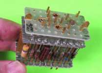
A fully socketed PCB IS a breadboard, of sorts.

With it, I stick the populated-socketed-PCB in an enclosure and take it over to my friend-with-the-golden-ears for further circuit tweaking, and if he still gigged, he could take it to the gig and try it in the heat of Sonic-Battle...


Now...
...Back to perf layouts.
 
Im assuming that GPCB Roto-Tone board is a mod board. I have one of those and they definitely come in handy even while using a breadboard. I can keep playing and turn the rotary switch to instantly hear the different in components.
 
Before I even had a breadboard, I socketed an entire GPCB EMEXAR PCB.
It still gets used as I'd rather grab it than lay out a breadboard for a variant of that circuit — the layout of the socketed PCB is already done for you. There you go, that's the advantage over breadboarding a circuit, the layout is already done for you.
i can see your point.
it-seems-logical-spock.gif

but, have you ever had a set sockets fail on you?
i used to love sockets and thought they were the bees knees, but since i’ve had a few of them fail (after repeated use, in similar testing scenarios) i kinda try and avoid them where possible.
(because sockets will punish you for using thiccc leads)

alright time for a perf layout 😛
IMG_8438.jpeg
 
NOICE!

What's the layout for?


Never had any sockets fail me yet, but that's just a matter of time.

Also, anything that's super-socketed is not going on the gig-board, but is related to experimentation — once the desired results are established a fresh board is used to solder the components in. Also, same for socketed diodes — after a while you figure out which you like best and you just solder in the components = less chance of failure.

I'm not gigging/touring/otherwise... 😑
 
What's better about a series 1N5817 vs 1N4001 to ground? Or is that just a preference. Used to see 1N4001s everywhere but not so much these days
 
I think it's just design preference. They both accomplish the same goal (polarity protection), but go about it in different ways. I think any schottky diode will work there since they all have very low forward voltage.
 
I read somewhere about how the series way is just slightly better than going to ground.


Going to ground, some juice may still get to the circuit, whereas if the series diode blows, nothing gets through.

If ever I manage to come across the properly explained details again, I'll post them here.


It's kind of like 6v vs 12v in cars. There was nothing wrong with 6v per se, just that 12v gives you a little more cranking power to start the engine, — small details. Things change. We used to rent VHS movies from Blawk Bluster, now we stream them .... movies haven't changed.

Used to be bypasses didn't include LED-indication. Pretty much mandatory now.
 
The parallel 4001 is just old school. How often were they managing to plug batteries in wrong way around? It’ll work if you accidentally plug the wrong polarity in—for a moment. Won’t be long until it cooks and ain’t protecting shit. Series schottkey can handle way more amperage than necessary to run your average pedal. You lose less than 1/2 volt, and I’m pretty sure you’re not even hitting that upper limit til you get close to a full amp.
 
...If ever I manage to come across the properly explained details again, I'll post them here.
...
The parallel 4001 is just old school. How often were they managing to plug batteries in wrong way around? It’ll work if you accidentally plug the wrong polarity in—for a moment. Won’t be long until it cooks and ain’t protecting shit. Series schottkey can handle way more amperage than necessary to run your average pedal. You lose less than 1/2 volt, and I’m pretty sure you’re not even hitting that upper limit til you get close to a full amp.


Boomshakalah!
 
Of course, if a parallel protection diode fries you have no protection. Come on brain, I know you're in there
 
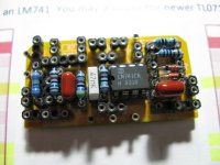
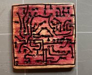
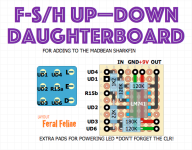
Thought I'd start a thread to share my layouts, get feedback on them, and hopefully have some fun.
This sub-forum seemed the logical place to knot the thread.

I use DIYLC for my perf-layouts (though I have Eagle) because I spent an inordinate amount of time learning how to use DIYLC and it's where I'm comfortable now — for the moment. Tried getting up to speed on Eagle a few times, but... maybe later.

I originally started doing perf layouts mainly because I wanted to build stuff that wasn't available on PCB and prefer perf to vero, another reason was I didn't think I had the skills or knowledge to lay out PCBs. However...
Now I'm getting back into perf layouts for some of those same original reasons, but also as a dojo to train up and prepare for laying out my own PCBs.
Ready or not here I come, PCB fabricators.


So, for the first thread-entry I've spent the last few days tinkering with a clean blend for @jrhevron and myself. Here's the first draught:


View attachment 98484

The perf above was put together based on the schematic in this PDF:
In turn, Fusion's based on Jubal81's Schooner.


Instigated to lay this one out by posts in this thread:


I chose to go for some added gain to the clean-blend, but haven't worked out the exact values yet. The PDF says


I don't quite get what a gain of "4" means. Four times the voltage? [EDIT: Yes, most likely a VOLTAGE-gain of 4 given the text just before mentions a voltage gain of 2; also, "R2=R3=47kΩ" must just mean both R2 and R3 are 47k, as per shown in the schematic Increase of 4dB? What does this compare to?/EDIT]
Nucleon's designer mentioned the same thing in a DIYSB thread, username ROCKHORST:

Any advice on sorting out the clean's GAIN would be welcomed.


INVERSION
Another feature of the circuit in the PDF is it can be built to invert the phase of the wet-signal.
I thought it'd be more utilitarian to have both inverting and non-inverting available at the flip of a switch, so I worked that out.
I've included a mockup of the switch with the perf layout, 'cause it helped me determine whether or not it was feasible to switch between inverting/non-inverting so it might help others, too. That switch took some time to figure out, but as is usually the case it was more straightforward than I thought.

The main layout itself positions the two pots and switch such that it should fit a 3-knob PedalPCB template with a little wiggling.
One pot's legs are oriented vertically and the other's horizontally, to give better support to anchoring the perf and avoid possible strain on solder joints that all pot-legs on the same axis are susceptible to. Bonus: it's more compact than having the pots side by side.

The control layout would look something like this, with the bypass LED:

🕕 📍

🕛


That's about it, for now. Wasn't able to sleep last night, so once again posting half drunk from sleep-deprivation 🥴 — I'll never learn.
I'm sure there will be errors in this post I'll have to fix later.


Thanks to Nucleon's Rutger Rockhorst for working up this clean-blend in the first place.

NEXT UP...
...I'll post a booffster: Just prior to the Nucleon Clean Blend, I mashed together Jerry Garcias Tiger Preamp with Mr Noir's Boosty Tigress.
I wonder if there would be any disadvantage to sending the signal straight to send before any part of the circuit. Id like to use it with fuzz faces. I suppose you could switch if you want the clean buffered or not before the send easily enough…
 
If you wanted to control a Fuzz Face from the splitter pedal, you could make a send/return loop — the FF would always be on and just brought in/out of the signal path via the splitter pedal BUT signal not yet actually split. Of course, then there's no "clean" signal, there's FF and FF+whatever.

Sorry in advance for my pedantic putzing, but this may be of benefit to neophytes to signal-splitting:
The DISADVANTAGE comes into play when you try to split the signal passively — which is akin to splitting a glass of water. Once you pour 1/2 the water from one full glass into a second glass, you have two half-filled glasses. In signal terms, you've now got two too-weak signals.
An active splitter "tops up the glasses" so both are full.

The way to make the whole mess play nicely with Fuzz Faces and other temperamental circuits is to install a buffer-buster in one side of the active buffer-splitter.

Signal gets split, dry gets buffered, second signal goes to buffer buster then to whatever Fuzz/unruly device.
With a toggle or footswitch, you could bypass the buffer-buster.


To make the whole shebang in the first para more versatile for effects other than just FFs, you could put an order switcher between the loop and buffer/splitter. Maybe make the buffer-splitter also a parallel/series thing with two loops... Gotta love DIY, tailor-fit circuits to your needs.
 
Back
Top