First Build, getting no sound. Sandspur Fuzz

Verbzilla

New member
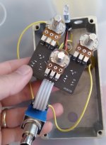
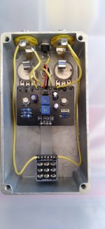
Does anyone see anything wrong from the photos? Pedal switches on with no sound. Bypass signal works fine and led comes on.

I think the transistor readings are way off. What would cause this?
Transistor readings with multimeter (volts)
Q1:
E 0, B.022, C.459

Q2:
E 0, B.459, C.442

Thanks for your help, I'm sure I must have screwed something up? Haha
 

Attachments

  • 20260927_131152.jpg
    20260927_131152.jpg
    199.4 KB · Views: 65
  • 20260927_165927.jpg
    20260927_165927.jpg
    227.6 KB · Views: 65
No offense @swelchy but OPs issue is voltage, not audio path. DMM is king at the moment.
I'm inclined to think you may have cooked a transistor. I would reflow all the resistors and bias trimmer before attempting to desolder the 108s.
First, make sure the fuzz pot is 1k.
Set the sundial and bias trimmer for maximum voltage/minimum resistance. Then post voltage for Q1 and Q2 C and B individually, DC negative to component. If we can't get to a working bias and component values are correct, BJTs are suspect.
 
If all else doesn't pan out and your in the states, you can send me the build and I'll troubleshoot it for you. If you want I'll just identify the fault and let you fix it or I can get it up and running for you. All you have to do is cover the shipping.
 
Thanks Swelchy, it might come to that... hopefully I can get it figured out with some work.

I will have some free time tonight to get all the leads trimmed and all the joints reflowed. I will then check both Q1 and Q2 and see if I get anymore voltage at their collectors. I will make sure to post my finding with photos.

Thanks everyone, this community is great!
 
Yeah my first thought was the footswitch … and then my next thought was the ribbon cable. A quick continuity test of the footswitch and the cable might not be a bad idea. The voltage issue is a bit of a head scratcher.

Edit to add - I’m a little rusty and was never that sharp so …
 
See if the circuit input is shorted to ground. You gotta be careful with ribbon cables - they can hide issues
Just so I do this correctly... Should i have the pedal powered on, black probe to ground and red probe to the input on the pcb? Looking for a specific voltage. Or is this with the pedal powered off with a probe on the input pcb pad and input pcb footswitch pad looking for continuity?
 
I think I figured out what to do. Pedal off. Black probe to ground. Red probe to input. Should not show continuity. Correct? Pardon my ignorance... haha

Well, bypass works fine so the input jack itself is not shorted to ground.

Depending on the switch positions, the PCB Input WILL be connected to ground in bypass.

What you want to verify is that when the LED is ON, the Circuit input is not grounded.
 
We're checking the input pin of the PCB, rather than the input jack itself.

You don't need the pedal plugged in to check for this. Set the meter to continuity and put one lead on the circuit board's IN solder pad and the other lead on any GND pad. If it beeps or gives you any number other than 1 or OL then your problem is the in is shorted to ground
 
We're checking the input pin of the PCB, rather than the input jack itself.

You don't need the pedal plugged in to check for this. Set the meter to continuity and put one lead on the circuit board's IN solder pad and the other lead on any GND pad. If it beeps or gives you any number other than 1 or OL then your problem is the in is shorted to ground

50% of the time it WILL be connected to ground. Which is why you should test with power to see when the LED is engaged.

With the LED ON, you know the circuit portion is active and if the circuit input pad is connected to ground, you have an issue.

In bypassed state on the switch, most builders, Robert included, short the circuit input to ground.
 
Back
Top