First build Trainwreck.. Derailer woes

rickn2112

New member
Hi all just completed my first build and guess what.. I have problems!!
On first plug in bypass signal perfectly fine.. switch on and nothing.. disconnect, have a coffee and look at the forum.. following general advice I had a good look over the board and tidied up a few solder joints.
Attempt #2
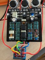
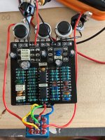
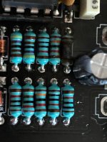
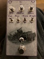
Reconnected and.. exactly the same except it starts smoking!!!!!! Power plug out and try to see what the hell happened.. the 10R resistor R2 I think has burned!! Can’t see any other ‘obvious’ damage but better minds may suggest what I should check (Remember I’m a total noob)

Can anyone see anything obviously wrong/stupid that might explain why this happened and what the solution may be?
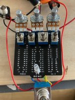
I should add, on testing continuity on the 3pdt I got a connection between the green(ground) and blue(out) wires when engaged which would suggest to me the effected signal is being sent to ground??
 

Attachments

  • 25874401-9EED-461F-85AB-A59FA655B42E.jpeg
    25874401-9EED-461F-85AB-A59FA655B42E.jpeg
    74.8 KB · Views: 21
  • 98BEB886-FFD1-44C5-AF9B-6FC8429C312D.jpeg
    98BEB886-FFD1-44C5-AF9B-6FC8429C312D.jpeg
    92.6 KB · Views: 22
  • 044BBF7A-A737-4AEC-8474-D1AF8DDF8309.jpeg
    044BBF7A-A737-4AEC-8474-D1AF8DDF8309.jpeg
    654.3 KB · Views: 19
  • C7C447E5-C81D-4B32-977E-50CD11421239.jpeg
    C7C447E5-C81D-4B32-977E-50CD11421239.jpeg
    74.9 KB · Views: 22
That was quick!! I must admit this is totally new to me, just a guitarist trying to save money!! Would a short on the 9v line explain the continuity between the blue out tab and ground? As a newbie I also find it incredibly hard to translate from the components identified on the pcb to the R1..10, C1..10, etc used in a schematic.. for someone like me it would be incredibly useful to have an image of the pcb, similar to the build docs, but with R1 etc identified.. would make troubleshooting/debugging much easier.

Thanks so much for the impressively fast response.. I’ll check the board again with these things in mind.. I’m assuming the red circles identify the +ive ends of the components?
 
Ahh glad you pointed that out, the image in the build doc is supposed to list the component locations, not the values.... I'll get that updated as quick as possible, but in the meantime here is the image.

What resistance do you measure between ground and the output wire when the effect is engaged? That wouldn't likely cause the resistor to have burned, but still might be worth investigating.

You didn't make the measurement with power applied by any chance? Resistance (and continuity) measurements won't be accurate with power applied to the circuit.


Board-RefDes.jpg
 
Ahh that’s better 😂
No power applied I read just about 10 ohms between out and ground with the effect engaged..
Got to say I’m impressed with the speed of your responses.. kick back and have a coffee
 
10 ohms is still low, you should be reading a minimum of 1K with the volume control all the way down, and somewhere in the neighborhood of 10K with the volume control all the way up.

Some DMMs don't show the unit on the display, if the Range is set to 10K it might just show "10" and the K is implied.

Regardless, I'd hunt down the cause of the burning resistor first, but keep this in mind if there are other problems later.
 
It does help if you check which scale you’re on!! Yep I’m getting just about 1k with volume off and a smidge over 10k with it full on.. at least that’s one thing to cross off the list
I’m going to swap out C2 and R2 when I can grab them (lockdown here in the UK) but in the meantime I’ll check the board closely and sort any issues I can find
Thanks for the help mate
 
Well it’s done and working!! Sooooo much gain though.. I used TL072’s, would the OPA give a different gain structure? Or would a log pot work to give a better range of control??

R2 and C2 replaced.. R2 burnt out the 2nd pad when it went so a bit of tracing to check if anything else was affected.. everything else seemed ok so I jumpered to the positive leg of C2.. not the prettiest but definitely works!!
Thanks for the help again mate
 

Attachments

  • D98A75E3-38CB-4455-A21E-1544807BA594.jpeg
    D98A75E3-38CB-4455-A21E-1544807BA594.jpeg
    72.4 KB · Views: 8
Back
Top