First PPCB Build! Add Voltage Starve To Executive a la Hephaestus?

Ginsly

Well-known member
First time posting here, but certainly not the first time perusing! Wow, incredible community here.

I recently made a Mask Audio Dark Grime 1-knob fuzz as my first build, and it thankfully went well. Tenth time soldering!

Just ordered some boards from PedalPCB, including the Executive (Bosstone). My favorite circuit, as I'm a huge Spirit fan.

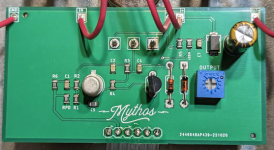
I'd love to add a voltage starve control to it like in the Mythos Hephaestus (it's the ONLY knob on that one). I realize the Trumpeter has something like that, and I plan on building one of those as well. I'd like to start with the classic Bosstone with just this one mod, though.

Sounds like some Bosstone-based pedals might have a transistor bias knob, while some (the Mythos?) have an overall voltage control. Please correct me if I'm wrong! Not sure how different the effect would be between those two options.

Any advice would be incredible, thanks!
 
Welcome to the forum and the hobby.
freaks-one-of-us.gif

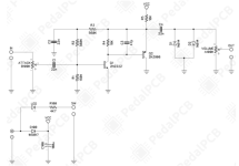
If you're okay with schematics, head over to madbean pedals and look at the snack shack buildoc, which is a DAM meathead but iirc also has bosstone values.
There's a starve on there. As always with mbp, good docs, good pcb, and good circuit.
A bias starve often adds a pot as a variable resistor in series with the bias resistor, usually for Q2, I think.
Voltage starve, or sag, decreases across the circuit, basically misbiasing everything.
 
I finally belong!! Ha… thx @jwin615

I’m learning, but.. not quite at the point where I can look at a schematic for one circuit and apply it to another as an external potentiometer. I did check out the Snack Shack just in case something clicked, but couldn’t even identify the voltage starve.

I think I need it spelled out ”for dummies” at this point, sadly!

Thanks for chiming in to help a beginner, much appreciated.
 
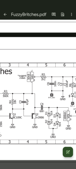
@Harry Klippton gotcha, I see it on the Fuzzy Britches schematic. Unfortunately I’m still lost as to what the practical steps would be in modifying the PPCB Exec board, though! Looks like the “sag” in the madbean FB is based on the Fuzzly Bear version of the Bosstone. I wonder if that’s the same approach as the “Danger” knob on the Hephaestus- or is one an overall starve and one a transistor starve? Can’t really tell…
 
I'm looking at this kinda quick on my phone and I should be sleeping, but it looks like the Madbean doc says to use a 250ka pot. You'll have to figure out which end of R5 on the executive connects to the emitter of Q2. Connect that end of R5 to the center lug of the 250k pot, and one of the outer legs to the emitter of Q2. Solder the other outer leg to the center one. Do you have a multimeter and do you know how to check for continuity?
 
@Harry Klippton - ha, I actually fell asleep 10 minutes after my last post...

Ah! Ok this is getting closer to what I can understand. So this is an "overall voltage" starve, and not a "transistor bias" control?

I do indeed have a multimeter and can check continuity. Where would I be checking? (I realize that would happen after populating the board, see below..)

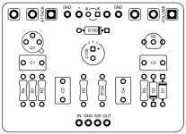
I'm also not sure how I would determine which end of R5 connects to the emitter of Q2, though. My guess is that would be easy to see on the schematic, but I'm still not sure how I would locate that point on the pcb itself. I actually haven't populated the board yet, as I wanted to see if this modification was easier to incorporate while building, rather than after. Not sure if the board needs to be finished before doing any of this, though.

Once I figure out how to determine the correct end of R5, I have a very, very "beginner" question - do I still install both ends of the resistor normally on the pcb and THEN link one end to the emitter of Q2? Or do I omit that resistor, as the A250K pot will kinda replace it? I plan on using transistor sockets, so I'm also not sure how things would look on THAT side of the equation either! Cram both in?

I commend you on helping a dum-dum like me, I'm trying to play catch-up as fast as I can with all of this! Ha... Truly appreciated. I think I'll get there. I can hear everyone shaking their heads... rightfully so! :LOL:
 
Last edited:
That's why I asked about checking continuity. You can do it before you populate the board. Put one probe of your meter on the emitter pad, and then you'll test each pad of R5 with the other probe. The pad of R5 that beeps with the emitter of Q2 is the one that's connected. Don't solder that resistor in on that end, but attach it to the center lug on your sag pot. Does that make sense?
 
Makes sense! That's great info, much appreciated.

It likely won't reach, so I'll attach the R5 resistor to the middle pot lug using a little wire, correct?

Just to clarify - after that, I attach (using some hookup wire) an outer pot lug to the emitter of Q2 and the other outer pot lug to the center leg of Q2?

Again, I'll be using transistor sockets - I wonder if a transistor leg and the wire leading from the A250K pot will fit in... Failing that, just solder the wires to the side of the transistor leads before I pop them in the sockets?

Thanks for your help, this is exactly what I needed!
 
Yes, use a little bit of wire to make the connections. You can solder the jumper to the transistor leg. I personally don't use sockets and don't advocate for using them but you do you
 
Gotcha, thanks Harry. I just wasn't sure if two of the transistor legs were attached to two of the pot lugs, but sounds like they are.

Seems like sockets are standard for ICs but not necessarily for transistors. Do you avoid them because there is less of a solid connection, or because they're simply unnecessary? I just like the idea of trying different transistors in circuits, at least when starting out.
 
No, only one transistor leg is attached to the sag pot. Again, trying to do this on my phone
1000001846.png


As for sockets, I think they cause more headache than they solve a lot of the time, or are completely unnecessary. The transistors in the executive are not expensive and are common so no big deal there
 
I'm just going off the Madbean fuzzy britches schematic for the sag pot. you can see the relevant portion below. Toward the top, you'll see the 2k2 resistor (also R5 on this schematic) going to the sag pot, then the other end of the sag pot makes a connection going down. That point connects to the emitter of Q2 (with the little arrow on the schematic symbol), and it's connected to one end of C3/47pf capacitor, and one end of C4/68nf capacitor.

1000001847.png
 
One more thing. I just noticed that in the executive and madbean's stock bosstone schematic, R5 is 18k, but the kma fuzzly bear with the sag pot uses a 2.2k resistor there. I'd be inclined to use the 2.2k resistor when adding the sag pot but the technical details of that is over my head. Perhaps someone more knowledgeable can chime in on that
 
Ah ok - when you originally said "Solder the other outer leg to the center one" I guess I'm not sure what that means, then. Solder two of the pot lugs together?

So, in practical terms this is where I'm up to:

- Install R5, but just one side (whether 18k or 2.2k, depending on what the consensus is)
- Attach the unsoldered side of that resistor to the center lug of the A250K using some hookup wire
- Attach a side lug of the A250K pot to the emitter of Q2 using some hookup wire
---
- Then do I attach the 3rd, unused pot lug to the center pot lug (which also has the resistor linked to it)? Is that what you meant?
- Also - Nothing ever leads back to that unused hole on R5?
 
- Also - Nothing ever leads back to that unused hole on R5?
Right. You're breaking that connection to add the pot.


- Install R5, but just one side (whether 18k or 2.2k, depending on what the consensus is)
You have to do the continuity test first to figure out which end will go to the sag pot


- Then do I attach the 3rd, unused pot lug to the center pot lug (which also has the resistor linked to it)? Is that what you meant?
Yes, that makes it a variable resistor
 
One more thing. I just noticed that in the executive and madbean's stock bosstone schematic, R5 is 18k, but the kma fuzzly bear with the sag pot uses a 2.2k resistor there. I'd be inclined to use the 2.2k resistor when adding the sag pot but the technical details of that is over my head. Perhaps someone more knowledgeable can chime in on that
I like to use a 1k resistor and a B50k pot here. The 1k pot limits the current through the pot and prevents it from burning out, but you can still get everything from a stock Bosstone to a Fuzzly Bear to some of those gnarly octave down tones that you get from a Trombetta/Bone-type fuzz. I I find that for R5, the range of useable tones starts at 1k (maybe even lower, but I've never gone below 1k) and tops out at around 80k or so, so a 100k pot will have a range at the top of the dial that isn't really useable. If you want the last 30k or so that you don't get with a 1k resistor and a 50k pot, you can put R5 on an SPDT like the Trumpeter does, and have the switch alternate between 1k and 33k resistors for R5. But at that point you might as well get the Trumpeter. TBH, you should do that anyway because you can't have too many Bosstone variants around.
 
Back
Top