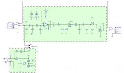
I see on the schematics I chose at random that the footswitch is labeled SW or SWGD and shows two circles, in the part of the circuit that takes the LED to ground. So if the switch is on, the LED lights up. But I am not seeing any other pole of the footswitch on the schematics, just the LED pole. Shouldn't the other pole be disconnecting the input? It looks to me like the whole pedal is turned on (Vcc and Input) whether the footswitch is on or off. Here is an example - Muroidea
You are using an out of date browser. It may not display this or other websites correctly.
You should upgrade or use an alternative browser.
You should upgrade or use an alternative browser.
Footswitch and schematics
- Thread starter DDad
- Start date
RobotZombie23
Member
Yes I believe pedals are always powered as long as the power is plugged in. The footswitch just bypasses the signal.
jimilee
Well-known member
That’s exactly it. The board send is grounded in the “off” position.Yes I believe pedals are always powered as long as the power is plugged in. The footswitch just bypasses the signal.
Robert
George Cloney
The bypass switching typically isn't part of the schematic when it isn't part of the circuit / PCB.
You see the SW and GND pad because they are used to illuminate the LED, which is on the PCB itself. The LED, current limiting resistor, and SW/GND pads are physical parts of the circuit.
A builder might choose a footswitch, a relay, some sort of electrical or optical bypass, or to hard-wire the circuit always-on. The schematic shows the circuit, how you activate/bypass/power it is entirely up to you.
The wiring diagram on the other hand, typically does show a standard straightforward true-bypass scheme using a 3PDT footswitch.

