Fornicus LEDs

sticky1138

Well-known member
I'm working on the Fornicus and I'm a little confused by the LED configuration.

On the PCB, there are three spots for LEDs, each unlabeled. In the doc, D1 is yellow, D2 is red, and I assume the third LED on the PCB is the bypass LED. From looking at the schematic, I believe the yellow is the center spot by the IC, the status LED is lower left by the 3PDT footswitch, and the red is by the momentary switch.

Since the doc says D2 is "external," I assume that means the red LED lights up when the momentary switch is held down?
I made one of these (not from PedalPCB) and D2 lights up when you play guitar, it reacts to your signal if you are in sag mode. It'a a part of the signal and isn't necessarily on when you push the momentary switch. One of the trimpots affects how bright it is.

The yellow D1 which is internal just seems to be always on. I'm sure it does something, but I have no idea what.
 
I was thinking it would be weird if the momentary switch had a status LED. You would know when it's on because your foot is on it, plus your foot would cover up the LED.
 
Looking at videos of the original pedal, I believe that the momentary LED has a couple of functions depending on the sag switch setting. It lights up when in sag mode (when the momentary switch disengages the sag function).

The original also lights brightens and dims with the signal as set by the threshold pot.
 
Regarding the LED I remember Brian posting this over at FSB:

Nocentelli wrote:Despite reading about the "dynamically modulated sag feature", I can't help looking at the collection of separate transistors and jfets and thinking "several boosters strung in series": is the dual pot the gain control?
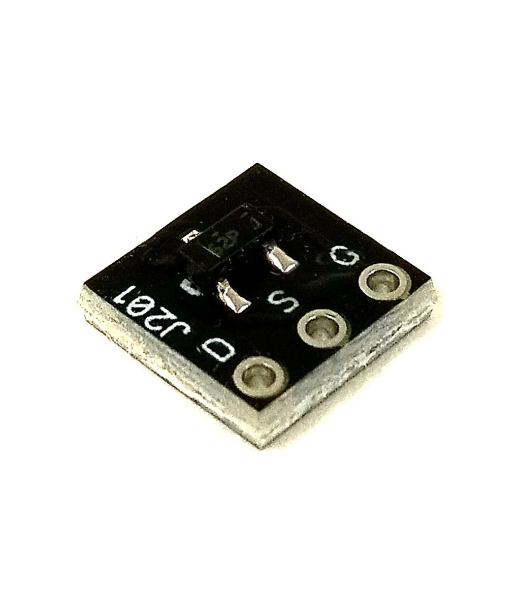
the f@ck is 3 jfet (2 j201, 1 2n5457) gain stages in series with the dual pot (gain) controlling the volume of the first 2. final 2n5089 is an emitter follower. SWTC for the high-cut control. the rest of the components are for an envelope follower aka the "dynamically modulated sag feature". it's modulating the voltage on the 2n5457 for the crackle and gnar gnar... i tried modulating each different stage, two at a time and all three but the particular stage was the best choice for a number of reasons.
jonasx26 wrote:Hmm.. Looks like the yellow LED anode is connected to pin 5 of the TL072.
Bet its used for the offset-bias-trick used in many envelope-followers. Dr. Q etc..
:)
right you are.
 
Does anyone have a successful build on this one? For me, the yellow (internal D1) LED is constantly on, and then the red is like everyone said where it seems to only be used when Sag is on or temporarily with the switch when Sag is off.

That being said, it doesn't seem to change the sound much so I'm wondering if I made a mistake somewhere?

Mine seems to be working fine. Yellow led is always on for me too.

If the red led goes on but doesn’t impact your round I’d look at r22. You may have the wrong value here. I put a trimmer here and found that there was a narrow area that it actually worked. I settled on 1k5 anyway

Or you could check threshold/trim1. These let the sag sound through
 
Awesome thanks!

Would you say that the higher the internal trim the more the sag sound comes through?


Also having a hard time hearing the difference in sound with the weight switch but that could just be a me thing.
 
Awesome thanks!

Would you say that the higher the internal trim the more the sag sound comes through?


Also having a hard time hearing the difference in sound with the weight switch but that could just be a me thing.
Yeah the internal trim is a bit of a waste for me. I just have it fully on. Full clockwise (for mine anyway) has max sag. You can actually see the boom LED light up/decrease when you turn it.

On my build there is a huge difference in the weight switch with heavy being very saggy and light being mild. I actually replaced the light capacitor with a 4.7uf to increase the sag on light.

The sag is more noticeable with the gain on low.

Mine isn't actually the PedalPCB version. I copied another schematic and made the PCB as PedalPCB didn;'t have one at the time.. However upon review the schematic is the same.

If you can't hear the sag with the gain down, i'd check your heavy/light capacitors. One should be 10uf. If R22 is correct then I'd check everything between C10 and Q6 on the schematic to make sure you have the right values. That's the sag part.
 
This is so incredibly helpful!!! Thank you!!!
I am having similar issues where the sag circuit seems to do a whole lot of nothing, including at lower gain settings.
The only way I can even even get halfway close to a what the original pedal sounds like with the sag circuit is to put a jumper across where D2 should go, but even then the change is very slight, no matter what I do with the Trim1 and Threshold settings.

Do we think that replacing R22 with a trim pot is really the ticket?
I've tried swapping out Q5 & Q6, but hear no change.

kid-A, did you ever get yours working properly?
I believe it's working now and what got me to this realization was looping a simple riff and putting the pedal after the loop to twist the knobs as the loop played.


This really helped me understand what the sag does. Try turning the volume all the way up and the gain all the way down. Then turn the threshold knob up and down slowly.
 
I found having r22 as a trim pot made it incredibly difficult to get the sag right. 1k5 was right for me.

What colour is d1? I found it didn’t work unless the led was yellow.

Also is d1 lit up constantly for you?

I put trim 1 and threshold on full, turn the gain down and it sags well especially on the heavy capacitor.
Yes, D1 was originally yellow 3mm, but that didn't seem to be working. I read someone else had better luck with a green LED so I removed it to add sockets. Sadly, I managed to fry that yellow LED in the process which was my last one and the green LED wasn't any better. I really need to get better at de-soldering.

But yes, D1 is indeed always on. Thanks for letting me know 1k5 is the way to go. I don't want to make even more of a mess of my board if that's not the problem. Maybe I'll try auditioning another TL072 in case there's something funny going on there.

The Dead End FX Copulator schematic lists voltages for the transistors. Mine seem a bit high on Q3 & Q4, but more concerning is the emitter on Q5 is reading 0.000V instead of 1.8mV. Should I be looking around there, perhaps?
 
Last edited:
Quick follow up - turns out it was a lousy TL072.
While I was at it, I tested a few LED combinations. Green LED in D1 seems to work pretty well, as does an orange one. Blue gets pretty extreme a 5mm UV sounds like it's shredding your speaker cone as you play. Seems the greater the difference in forward voltage between D1 and D2, the more 'sag'. I'm sure anyone who understands the math better than I do would say "duh!"

Thanks to those who chimed in and helped me figure this one out.
 
Back
Top