SOLVED Gain pot not working. Help please.

neiltheseal

Active member
Hi everyone.

I'm new here and relatively new to making pedals.

I just put together the Aion FX Sapphire (Blues driver standard not the galaxie mod) and am having issues with the gain pot. The issue is that it does not work at all.
The pedal works and all of the other pots work fine but there is absolutely no gain and the pot does nothing. Here is a video of what I mean.

Does anybody have an Idea why this might be?

One potentially obvious solution would be the pot itself. As the build docs (link here) indicate a dual gang right angled pot, but I could not find one of these so just used a non right-angled one and used wires to connect to the PCB. Although with an audio probe all 6 pins of the pot have an audio signal.

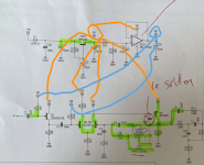
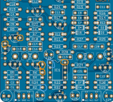
Here are some pics of the inside of the pedal and here is a pic of the schematic with my audio probe tracing. I did not completely audio probe the whole circuit as clearly it makes a sound, however I tried to look around the gain area to see where might be a problem and I am stumped.


Thanks in advance!
 
Hello, welcome !

What transistors are you using ? Could also be a pinout issue.

Are you sure all transistors and adaptors are correctly oriented on the board ?
Yes I'm sure all of the transistors are correct and in the right direction. I have checked this a few times as part of my trouble shooting. I usually use sockets for transistors (as I did here) but had to solder the JFETs in as they would not fit in the sockets so I was extra careful.

There are 3 types I'm using which are in the build docs:
  • 2SK209-GR JFET
  • 2N3906 BJT transistor
  • Q8 2N5088
How would I know If the gain pot is actually not working? I think that maybe since I soldered into those little circles that maybe I fried it? I've tried shorting pins 1 and 2 of the pot and this does not affect the circuit at all. I will have to order a new one.
 
The most obvious thing I see (in the pics) is that there appears to be no insulation on the two lower pots; those can easily come into contact with the solder joints beneath them and create unwanted shorts.
That's a good point. I do have some covers for those pots. I'll go put them on. However even when there is no connection (as right now they are bent forward) the gain pot still doesn't work.
 

IC1A - it's a part of the power supply section. So, no signal is OK. Make sure you have right voltages here - around 8.2-8.5V for the VA and half of the VA @ VB.

But.. I'd check the gain pot wiring first. You can remove the potentiometer and replace it with resistors - solder them between solderpads 1 and 3 of each section . Value of the resistor - 100-240k. The gain potentiometer is wired as variable resistor - higher value=more gain.
Thanks. I'll check the voltages.

Good info about the gain pot. I suspect I have destroyed the pot so I will try this!
 
Before I went about removing a dual gang pot I would be measuring it. Power off. Multimeter on ohms setting connected to the wiper and and end (the end in use). Turn the dial and measure each gang. You should get a sweep through the range from 0 to 250k (if using a 500k pot remember there are parallel resistors so you will still measure to 250k). The sweep won't be even - they are analog pots so one side will be slow rising and the other fast. If both gangs measure OK then I would look for the problem elsewhere for now.
 
Pot is wired here, so removal should be no problem. Check the pot (still wired) - if it reads ok, then measure the same but on the pcb solder pads. This way you can eliminate wiring issues.
 
Before I went about removing a dual gang pot I would be measuring it. Power off. Multimeter on ohms setting connected to the wiper and and end (the end in use). Turn the dial and measure each gang. You should get a sweep through the range from 0 to 250k (if using a 500k pot remember there are parallel resistors so you will still measure to 250k). The sweep won't be even - they are analog pots so one side will be slow rising and the other fast. If both gangs measure OK then I would look for the problem elsewhere for now.
Thanks. I tried this and no measurement from the gain pot whatsoever. The other 3 pots measure roughly the correct resistance per what is written on the pot.

Looks like this is it. I’ll solder some resistors on this afternoon and see.
 
IC1A - it's a part of the power supply section. So, no signal is OK. Make sure you have right voltages here - around 8.2-8.5V for the VA and half of the VA @ VB.

But.. I'd check the gain pot wiring first. You can remove the potentiometer and replace it with resistors - solder them between solderpads 1 and 3 of each section . Value of the resistor - 100-240k. The gain potentiometer is wired as variable resistor - higher value=more gain.

I removed the gain pot and replaced it with 2 x220k resistors like in the pic below.


It definitely had an effect and there is def some gain there. Although I thought that with 220k being the upper limit there would be more gain.

Below is a video. Does this seem about right?

 
IC1A - it's a part of the power supply section. So, no signal is OK. Make sure you have right voltages here - around 8.2-8.5V for the VA and half of the VA @ VB.

But.. I'd check the gain pot wiring first. You can remove the potentiometer and replace it with resistors - solder them between solderpads 1 and 3 of each section . Value of the resistor - 100-240k. The gain potentiometer is wired as variable resistor - higher value=more gain.

I checked the voltages and they seem a little less than what you have posted here. Is that an issue?

Va was consistently 7.74 v on pin 8 of the ic, d of q5, q4 and q3. Was 7.09 on r6 and 8.48 on c27.

I checked vb at r2, r4 and pin1 of ic and it was 3.87 so exactly half.

Voltage coming from dc input pin was 8.73.

Do these seem in range? The gain was less than I expected but that might just be me.
 
I don't know if that is the maximum gain you are supposed to get. I don't have one. I do know that I like the sound though. Will definitely consider for my next order. Can you end up with too many drive pedals?
 
Although I thought that with 220k being the upper limit there would be more gain.

I'd expect more gain but I'm not familiar with the BD-2. Check some youtube demos.
You can also use software oscilloscope (Visual Analyser) and a phone as a signal generator and compare your readings with the simulation results from the site referred by @Mcknib (post #13)

I checked the voltages and they seem a little less than what you have posted here. Is that an issue?

Do these seem in range? The gain was less than I expected but that might just be me.

Your V readings are OK.
 
I built the Sapphire, i do have much more gain available, using 2sk209 like you. I had a similar issue with the galaxie mod, but not with the standard version. Your build sounds like the gain pot is in the first half of the rotation.

This circuit is able to go in the distortion territory quite easily, at least in the Gain pot's last quarter of rotation. With quite a considerable amount of low frequencies (I had to mod mine to roll back a bit of low ends).

I 'll suggest to post your readings on your transistors with the gain fully CW.

Edit : I just noticed you soldered the adaptors legs on the sockets. You are supposed to fit your transistors in the sockets without solder. The legs you chose for your adaptors are probably too large to fit in sockets, I think I recognize them and had a similar issue. This way there might be a bad connection. I would change all adaptors legs for thinner ones that can fit sockets, and with a desoldering pump, I'd try to clean or replace all sockets.
 
Last edited:
Back
Top