General Tso’s green LED

manfesto

Well-known member
(Dunno if this belongs under “Troubleshooting” or “Mods” since I’m not sure what the original circuit had, but)

Built the General Tso’s yesterday and I thought it was way too subtle a compressor, even for an optical comp; I know the original Fat General is known for transparency and for not pumping, but I just found even with sustain full-up I was barely getting any compression at all.

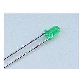
I’d built it with these green diffused LEDs from Tayda, which peak at 2,000-3,000 MCD


Wondering if maybe that was too dim for the LDR, I went to my local parts shop and got these 11,000 MCD waterclear green LEDs:


And now the circuit works as expected; I’m getting the transparent sustain I was expecting from watching demos.

I can’t find a gutshot of the Fat General anywhere; does anyone know what kind of green LED they used?
 
Show u a pic of how you have the LED & LDR aligned.
The MCD number by itself is not all that meaningful because
A) It is measured at a current much higher than we would use in a guitar pedal.
B) It does not take into account the radiation pattern.
I think that what makes the clear LED more effective than the diffuse LED is that more of the light that comes out lands on the LDR, rather than radiating in every direction.
2417F4E1-1740-4E1D-B7D2-EBE4E338E1C0.jpeg Same way I’ve done LEDs/LDRs in the past, basically touching.

Didn’t know that about MCD measurements! Numbers aside, visually, the clear LEDs are brighter with a longer fade to dark than the diffused LED were DAB7C82F-F1CA-437F-B44C-7E4028EA436F.jpeg
 
In the original the lens of the LED is pointing directly at the face of the LDR.

However, they were enclosed in heat shrink tubing so although the color of the LED was visible it wasn't possible to identify whether they were diffused or clear... You could very well be correct. (This was a loaner pedal so I couldn't attack it with a scalpel)
 
I would like to modify my statement "...what makes the clear LED more effective than the diffuse LED is that more of the light that comes out lands on the LDR..." because you have the majority of the LED's output directed away from the LDR. It would be much more effective if the LED's radiation pattern was pointed toward the LDR. I.e. the nose of the LED facing the LDR. Most of the light landing on the LDR in your pic is scattered around the reflective surfaces inside the LED.
The human eye, like the ear, responds logarithmically. The fact that the light is brighter and focused on the observer creates the perception that the fade to dark is longer.

Nice build!
 
It would have been Good to find out how the Diffused LED's worked with Shrink over LED & LDR as all the light is captured by the LDR.
Even the original Dinosaural had Vactrols that are Enclosed so I would say it was a given to Cover these also.
When I built the Magnatone vibe clone pedal I had to Shrink Wrap it.
 
It would have been Good to find out how the Diffused LED's worked with Shrink over LED & LDR as all the light is captured by the LDR.

I generally don't cover my LED/LDRs. In this case the two are working in parallel so I did to prevent any optical coupling between them.

I built the prototype with diffused green LEDs (and it worked fine, but maybe a bit subtle). I'm going to order some clear green to compare.
 
It would have been Good to find out how the Diffused LED's worked with Shrink over LED & LDR as all the light is captured by the LDR.
Even the original Dinosaural had Vactrols that are Enclosed so I would say it was a given to Cover these also.
When I built the Magnatone vibe clone pedal I had to Shrink Wrap it.
I actually ordered some vactrols off of eBay a few days ago to try out in this one, same ones that were in the Dinosaural too (VTL5C4).

Odds are I won't get them for a *bit* though :/
 
I actually ordered some vactrols off of eBay a few days ago to try out in this one, same ones that were in the Dinosaural too (VTL5C4).

Odds are I won't get them for a *bit* though :/
Can you try a before and after Test with & without Shrink, I think there might be some difference.
Even some black Insulation tape would work for TEST purposes.

Cheers music6000
 
If the covering is black, then it's not reflective and it will not direct any more light back to the LDR than having no cover at all. The purpose of potting the LED / LDR is to keep them aligned and to keep out stray light. Once the LED & LDR are mounted securely on the board and the box is closed, it will work the same as if they were wrapped in heat shrink, electrical tape or epoxy.
 
If the covering is black, then it's not reflective and it will not direct any more light back to the LDR than having no cover at all. The purpose of potting the LED / LDR is to keep them aligned and to keep out stray light.

This one has two LED/LDR pairs, my concern was stray light from one affecting the other.... They are working in tandem though, so it probably isn't a huge issue anyway.
 
I found some hosing on Amazon. There's different ID sizes, but I'm thinking about a circular PCB for the LED and Photocell (compatible with both) that is sized to fit perfectly in both ends of some cut hose.

Or maybe the PCBs sit flush on the ends of the hose and you use heat shrink to hold it all together.

Edit: Found some motorcycle spoke covers with 6mm ID. They're slit along the axis, so you could just pop in the circle PCBs and maybe heat shrink for stability.

Another edit: And here are some heavy duty black straws. These might need to be sawed, but the ID looks to be around 6mm. Here's the same diameter in thinner material.
 
Last edited:
I only have 3mm clear green leds. Will those work if I orient the tip toward the face of the ldr? Otherwise lol just use the diffuse 5mm greens I have
 
If only it were so simple!

I'm in the process of building the Delegate. I have a pile of LEDs and LDRs, so I set up a little test station to figure out which LDRs and LEDs work the best. If you have a protoboard and a handful of parts, you can do the same. In its simplest incarnation, all you need is a pot and a resistor to set the LED current and an ohmmeter to monitor the LDR resistance. Different circuit needs the LDR resistance to cover different ranges, so it helps to know the LDR's performance requirements. In the Tso, the LDRs are in parallel with the 100K SUSTAIN pot. As long as their dark resistance is at least 3x larger than the SUSTAIN pot, that's sufficient. Because the LDRs are in parallel, each one should be at least 6x the SUSTAIN pot. At the other end of the range, the LDRs need to get down to 10K or below. The LED current in the Tso ranges from zero to about 4.5mA.

In addition to measuring light and dark resistance, I wanted to measure response time, because LDRs go from low resistance to high resistance fairly slowly. For that, I used the function generator and scope functions in my LabNation USB scope and an opamp to drive the LED. Here's shots of the test station and the LDR performance. The green trace is LED current, 1V = 1mA. The blue trace is LDR voltage. The LDR makes a voltage divider with a 100K resistor and the 9.3VDC power supply. I got the best performance using a frosted blue LED. Ble may not be the best color for LDRs, but because it was bright and diffuse it worked very well. I tried a yellow LED with a high MCD rating, but because the light was focused in a narrow beam it was useless at a right angle and even straight on, it only illuminated part of the LDR. I also tried some green LEDs, but they were nowhere as bright as the blue LED seen in the pic below, even at twice the current. I also tried some while LEDs. They worked, but were not diffuse. In the scope plot, the LDR resistance varies from just under 2K with 1.42mA LED current to about 450K with the LED current at zero. I had a cardboard box over the test station to keep out stray light, but some still leaked in. In total darkenss, that LDR is over 2Meg. The time for the resistance to get from 2K to 200K is about 125ms. The slow response is what makes LDRs suitable for pedal applications like phasers, VCFs and compressors, but in the case of compressors, we don't want them to be too slow. This one should work well in the Delegate.

LDR test 02.JPG


LDR Test 03.png
 
Chuck—just brilliant! I'm sorting trough 50 LDRs to try and match two sets of 6 as closely as possible—and have everything worked out in terms of tracking the resistances, but couldn't decide the best way to measure transition speed (with a gut sense that this was maybe the more critical parameter, and definitely so in your optical compressor scenario). And I can just compare print outs, rather than making lists of tiny numbers on a strip of masking tape.
 
Back
Top