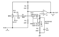
Hey folks, thought I would give GPT-5 a go at some (?simple) circuit analysis. I'm not a circuit wizz myself so not sure how well it did but here is the analysis.
You said:
how is the frequency range determined in this circuit

You said:
yes please
I would like to create two controls, one with roughly 200hz to 1khz, and another with roughly 500hz to 5khz
You said:
how is the frequency range determined in this circuit

ChatGPT said:
Great question — this is a midrange active bandpass filter (very similar to the Fender/Marshall tone stack mid control with a sweepable center frequency). Let’s break it down:
1. What kind of filter is this?
- The op-amp (A1) is wired as an active bandpass / peaking EQ stage.
- The resistors (R1, R2, R3, R4) and capacitors (C1, C2) form the frequency-selective network.
- RV2 and RV3 are dual ganged "frequency" pots (reverse-log) that sweep the effective RC ratio, shifting the center frequency.
2. Center frequency formula
The “frequency” section (R1, R2, RV2, RV3, C1, C2) behaves like a state-variable filter.
The approximate center frequency fcfc is set by the resistor–capacitor product:
fc≈12πReqCfc≈2πReqC1
- CC is mostly defined by C1 (15 nF) and C2 (6.8 nF).
- ReqReq is the effective resistance from RV2, RV3, R1, and R2 as the pot sweeps.
- As you turn the frequency knob, the resistance path between the capacitors and ground changes → shifting the “resonant” point.
3. Range determination
So:
- Capacitors C1 and C2 set the overall scaling. Larger C → lower frequency range; smaller C → higher.
- Pots RV2 & RV3 (100k RLOG each) set how far the resistive divider can swing → determines the sweep width (span).
- Resistors R1 and R2 (6.8k each) prevent the frequency from going all the way to DC or ultrasonic → they set the limits of the sweep.
fmin∼12π(Rmax)C,fmax∼12π(Rmin)Cfmin∼2π(Rmax)C1,fmax∼2π(Rmin)C1
- Lower limit of the sweep is roughly when RV2, RV3 are at maximum resistance (so ReqReq is large).
- Upper limit is when RV2, RV3 are at minimum (so ReqReq is small).
- The actual band of frequencies is roughly:
where Rmin/maxRmin/max are set by the pot values plus the fixed resistors.
4. The “MID” control (RV1)
- RV1 adjusts the gain (boost/cut) of the mid band.
- At center frequency, it either attenuates or boosts relative to the bypassed signal.
In summary:
The frequency range is determined by C1, C2, R1, R2, and the sweep of RV2 & RV3. Increasing C1 or C2 lowers the entire sweep range; increasing R1/R2 also lowers it. The dual-ganged frequency pots slide the effective RC ratio, sweeping the band center from low mids to high mids.
Do you want me to actually calculate the approximate sweep range (in Hz) for the given values (15nF, 6.8nF, 6.8kΩ, 100kΩ pots)?
You said:
yes please
You said:ChatGPT said:
Here’s a ballpark sweep for the parts shown (C1 = 15 nF, C2 = 6.8 nF, R1 = R2 = 6.8 kΩ, RV2 = RV3 = 100 kΩ R-log).
Treat the “FREQ” pair as varying the effective resistance seen by the caps from roughly Rmin ≈ 6.8 kΩ (pots near CW) to Rmax ≈ ~100–107 kΩ (pots near CCW). Using the usual f≈12πRCf≈2πRC1:
Because the mid-peaking network uses both caps, the practical center-frequency sweep ends up roughly in the ~150 Hz to ~3.4 kHz range, with most of the musical action ~200 Hz–2 kHz.
- Using C1 = 15 nF:
fmax≈12π(6.8 k)(15 nF)≈1.56 kHzfmax≈2π(6.8k)(15nF)1≈1.56kHz
fmin≈12π(106.8 k)(15 nF)≈100 Hzfmin≈2π(106.8k)(15nF)1≈100Hz- Using C2 = 6.8 nF:
fmax≈12π(6.8 k)(6.8 nF)≈3.44 kHzfmax≈2π(6.8k)(6.8nF)1≈3.44kHz
fmin≈12π(106.8 k)(6.8 nF)≈219 Hzfmin≈2π(106.8k)(6.8nF)1≈219Hz
How to shift the range:
- Double C1 and C2 → halves the whole sweep.
- Halve them → doubles the sweep.
- R1/R2 larger → lowers both ends; smaller → raises both ends.
I would like to create two controls, one with roughly 200hz to 1khz, and another with roughly 500hz to 5khz
ChatGPT said:
Awesome—here are concrete parts that will give you two sweepable mids close to your targets. I’m using the same simple f≈12πReqCf≈2πReqC1 read of this network, with the FREQ pots (dual-ganged 100 k RLOG) sweeping ReqReq from about Rmax≈106.8 kΩRmax≈106.8kΩ down to RminRmin set by the fixed resistors (R1, R2).
Low-mid control ≈ 200 Hz → 1.06 kHz
Result (calc):
- Keep C1 = 15 nF
- Keep C2 = 6.8 nF
- Change R1 = R2 = 22 kΩ (sets Rmin≈22 kΩRmin≈22kΩ)
- Dual 100 k RLOG FREQ pots as shown
High-mid control ≈ 500 Hz → 5 kHz
- fmin≈12π⋅106.8k⋅6.8nF≈219 Hzfmin≈2π⋅106.8k⋅6.8nF1≈219Hz
- fmax≈12π⋅22k⋅6.8nF≈1.06 kHzfmax≈2π⋅22k⋅6.8nF1≈1.06kHz
Result (calc, with C2 = 3.0 nF):
- Set C1 ≈ 6.8 nF (keeps the C1:C2 ratio similar to stock)
- Set C2 ≈ 3.0 nF (use 3.0 nF; 3.3 nF gives ~450 Hz–4.8 kHz)
- Set R1 = R2 = 10.7 kΩ (10 k + 680 Ω in series is perfect)
- Dual 100 k RLOG FREQ pots as shown
How to build it
- fmin≈12π⋅106.8k⋅3.0nF≈497 Hzfmin≈2π⋅106.8k⋅3.0nF1≈497Hz
- fmax≈12π⋅10.68k⋅3.0nF≈4.97 kHzfmax≈2π⋅10.68k⋅3.0nF1≈4.97kHz
If you want, I can sketch a quick switch matrix so you can flip between LOW MID and HIGH MID on one board.
- Either duplicate the whole mid stage (two op-amp bands, each with its own FREQ and MID/boost control), or use a switch (rotary or DPDT/3PDT) to swap the R1/R2/C1/C2 set between the low-mid and high-mid values above.
- Keeping the C1:C2 ratio roughly the same between modes preserves the “Q/shape” feel; R3/R4 can stay as in your drawing unless you want a different Q/boost amount.


