Grounding with 3PDT Order Switch

greypilgrim76

Active member
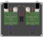
Quick question. I'm getting ready to start on my first two-pcb-in-one-enclosure project (combining a Blues Driver and Notaklon), and I'll be using the 3PDT Order Switch breakout board for the first time. The wiring diagram on the switch page is great for layout almost everything out:


1784765622078.png
But, the one thing I don't see is how to wire the grounds for each pcb. Should I just run the wires for each pcb to the input and output ground tabs as usual and just have two wires attached to each, or am I missing something really obvious here? (I always think I'm starting to understand electronics, and then I get stumped by something really simple like grounding...)

Anyway, thanks for any guidance!
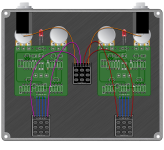
 
If you ground both PCBs to the power jack you should be fine. Just ground the phone jacks yo the nearest ground pad. It's basically like daisy chaining two pedals together, but all the wiring happens inside the enclosure.
 
Last edited:
Quick question. I'm getting ready to start on my first two-pcb-in-one-enclosure project (combining a Blues Driver and Notaklon), and I'll be using the 3PDT Order Switch breakout board for the first time. The wiring diagram on the switch page is great for layout almost everything out:


View attachment 121325
But, the one thing I don't see is how to wire the grounds for each pcb. Should I just run the wires for each pcb to the input and output ground tabs as usual and just have two wires attached to each, or am I missing something really obvious here? (I always think I'm starting to understand electronics, and then I get stumped by something really simple like grounding...)

Anyway, thanks for any guidance!

There are a number of different ways you could do it, but the way that @Aleph Null described is as good as any and will keep your wiring comparatively simple for a tidy build.
 
If you ground both PCBs to the power jack you should be fine. Just ground the phone jacks yo the nearest ground pad. It's basically like daisy chaining two pedals together, but all the wiring happens inside the enclosure.
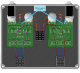
So if I'm reading this right, it would look something like this? (Or am I misunderstanding? Always a possibility!)
IMG_8788.jpeg
 
View attachment 121373
Your pic would probably work (I think they all go to a ground plane), but I think this is what @Aleph Null was describing.
Ah, I was this close. :)

So then, would I just leave the left ground tab on the right-side pcb and the right ground tab on the left-side pcb empty? (I'm guessing that those are both used on a normal single pcb setup to complete the ground, but here it's being completed elsewhere?)
 
All three of the ground pads at the top of the board are directly connected together so either way will work and are electrically identical.

(I'm guessing that those are both used on a normal single pcb setup to complete the ground, but here it's being completed elsewhere?)

Normally you have two 1/4" jacks and one DC jack per PCB. (Three ground connections total)

In this case you're omitting the output jack from the first pedal, and the input jack from the second pedal, so you have a pair of ground pads left over.
 
All three of the ground pads at the top of the board are directly connected together so either way will work and are electrically identical.


Normally you have two 1/4" jacks and one DC jack per PCB. (Three ground connections total)

In this case you're omitting the output jack from the first pedal, and the input jack from the second pedal, so you have a pair of ground pads left over.
See, this is the quality content I come here for. :) I feel like I'm starting to get a clear sense of how grounding works, but I didn't realize all of the grounds are connected. (*Reminds self for 100th time to always check schematic before asking questions*)
 
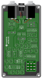
A follow-up question. I'd forgotten that the Notakliche has its own special breakout board and the in, out, and ground are routed to the top of the board:

1784824769890.png
In this configuration, I'm assuming that I just send one of the ground pads to the ground tab on the audio jack on that side of the pedal, per @genXslacker 's diagram above, but I'm not 100% clear regarding the connection between the "IN" and "OUT" pads at the top of the PCB and how they connect to "S2" and "R2" on the order switch breakout board. I'm thinking "IN" goes to "R2" and "OUT" goes to "R1," but I figure there's a 50/50 chance I've got that backwards.

Sorry for stacking questions on questions, but, to quote Henry Jones, Sr., "This is a new experience for me." :)
 
A follow-up question. I'd forgotten that the Notakliche has its own special breakout board and the in, out, and ground are routed to the top of the board:

View attachment 121378
In this configuration, I'm assuming that I just send one of the ground pads to the ground tab on the audio jack on that side of the pedal, per @genXslacker 's diagram above, but I'm not 100% clear regarding the connection between the "IN" and "OUT" pads at the top of the PCB and how they connect to "S2" and "R2" on the order switch breakout board. I'm thinking "IN" goes to "R2" and "OUT" goes to "R1," but I figure there's a 50/50 chance I've got that backwards.

Sorry for stacking questions on questions, but, to quote Henry Jones, Sr., "This is a new experience for me." :)


Not clear enough.
You said "'IN' goes to 'R2'" — referring to the klone's circuit?

If the Klone is on the left in Robert's SWAPPER diagram, then no.

"R2" stands for RETURN 2
"IN" of the Kliché needs to come from order-swapper's "S1" as in "SEND 1"

S1 & R1 go together for circuit 1, in this case the Kliché
S2 & R2, likewise, go together to route the Cobalt's signal.

It'd be more clear if things were marked by circuit A and circuit B:
AS & AR (Circuit A Send and Return)​
BS & BR (Circuit B Send and Return)​
But I guess Robert doesn't want any BS in any of his offerings.


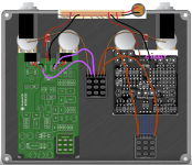
If you don't get one of Robert's Nifty-Super-Coolio-Daddyo DC-JACK BREAKOUT BOARDs, another cool trick is to use a bit of vero to perform star-grounding with multiple wires, comme ça:

NOTAKLICHÉ & COBALT ORDER-SWITCHER WIRING PEDALPCB.png
 
Not clear enough.
You said "'IN' goes to 'R2'" — referring to the klone's circuit?

If the Klone is on the left in Robert's SWAPPER diagram, then no.

"R2" stands for RETURN 2
"IN" of the Kliché needs to come from order-swapper's "S1" as in "SEND 1"

S1 & R1 go together for circuit 1, in this case the Kliché
S2 & R2, likewise, go together to route the Cobalt's signal.

It'd be more clear if things were marked by circuit A and circuit B:
AS & AR (Circuit A Send and Return)​
BS & BR (Circuit B Send and Return)​
But I guess Robert doesn't want any BS in any of his offerings.


If you don't get one of Robert's Nifty-Super-Coolio-Daddyo DC-JACK BREAKOUT BOARDs, another cool trick is to use a bit of vero to perform star-grounding with multiple wires, comme ça:

View attachment 121466
Okay, this is super-helpful! The only difference is that my enclosure is drilled for the pcbs being on the opposite sides, but I'm assuming in that case that the Notakliche's "IN" would just connect to the breakout board's "S2" instead of "S1," and then likewise with "OUT" going to "R2" instead? (I'm turning the switch to the side so that the switch itself points to the first pcb in the chain. At some point, I guess I'll have to figure out which direction to point it.)

I actually did order one of the DC jack breakout boards, so I'm assuming that as long as the black wires in your diagram go to one of the three negative pads and the red wires go to the positive pads, it'll be good to go? (And then just ground as in @genXslacker 's diagram?)

Sincerely, though--I didn't want to ask somebody to take the time to sketch out a diagram, but I'm super appreciative that both of you did. I'm still more visual than theoretical in my understanding of pedal wiring, so this was really, really helpful! This place (and you guys specifically) continues to rock!
 
Last edited:
I'm assuming in that case that the Notakliche's "IN" would just connect to the breakout board's "S2" instead of "S1," and then likewise with "OUT" going to "R2" instead?

Yep!

And then just ground as in @genXslacker 's diagram?

That will work.

I'm super appreciative that both of you did. I'm still more visual than theoretical in my understanding of pedal wiring, so this was really, really helpful!

I'm glad my dumb ass could actually help somebody. If you keep building, the wiring will eventually become intuitive; but as you've noticed, there is a learning curve.

At the risk of telling you something that you already know, make sure that your audio jacks are torqued down well so that they make good contact with some bare aluminum on the inside of the enclosure. The enclosure itself needs to be connected to ground, and that's all it takes. In all but the rarest of cases, it gets the job done very well. To that end, if the inside of the enclosure is painted, either sand some of the paint off the inside where you stick the jack through, or use jacks like these. They have barbs that poke through the paint/powder coat when you tighten them down.
 
Okay, this is super-helpful! The only difference is that my enclosure is drilled for the pcbs being on the opposite sides, but I'm assuming in that case that the Notakliche's "IN" would just connect to the breakout board's "S2" instead of "S1," and then likewise with "OUT" going to "R2" instead? (I'm turning the switch to the side so that the switch itself points to the first pcb in the chain. At some point, I guess I'll have to figure out which direction to point it.)
...
Yup, just swap the boards as you noted with the NortaKlichy going S2 and R2, Coblat S1 & R1.

POINTING A SWITCH... see bottom of post.


I actually did order one of the DC jack breakout boards, so I'm assuming that as long as the black wires in your diagram go to one of the three negative pads and the red wires go to the positive pads, it'll be good to go? (And then just ground as in @genXslacker 's diagram?)

Yep.


Sincerely, though--I didn't want to ask somebody to take the time to sketch out a diagram, but I'm super appreciative that both of you did. I'm still more visual than theoretical in my understanding of pedal wiring, so this was really, really helpful! This place (and you guys specifically) continues to rock!

It's what we do, help each other out; and it might help someone else down the line that comes across the same sorta thang and sees your thread; AND it sort of helps clarify things in my own head by working it out/explaining it to others — a sort of self-edification (I'm still a newb!); AND it kinda pays forward all the help I've received — so the time is well spent.


Th' ol' SWITCHEROO...

Well there's a lot of posts that have covered it already, but to dig them out... AUUGH!

I'll send you to BuddytheReow's tutorial 'cause it's as awesome as Buddy is:


Next up is the Switch-Craft thread 'cause I'm sure it's been explained in there somewhere, too, but there may be other things of interest to you in future builds.


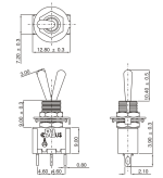
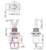
In a nutshell, using a SPDT switch diagram gleebed from BLMS...
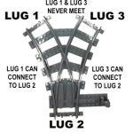
if the toggle-bat is pointing to the PCB on the LEFT, you connect that same PCB to the opposite lugs on the RIGHT, and vice-versa;
the centre lug is the common between the two:

datasheet-SPDT_On_On_Switch_-_Solder_Lug_-_Long_Shaft__76968 BLMS.png
⬇️
datasheet-SPDT_On_On_Switch_-_Solder_Lug_-_Long_Shaft__76968 BLMS directions.png


Y-TRAIN SPDT.png

Does that track?
 
Back
Top