Help Me Think Through A Substitute Question

BuddytheReow

Breadboard Baker
Hey All,

I'm working on a 200 Sunny Suns from Moonn Electronics. The link for the build doc is below. The build calls for 2 BAT85 diodes, which I don't have and don't really want to pay $7+ for shipping on $1 worth of parts. I think these diodes simply take any signal over the forward voltage and dump it to ground which is similar to a SHO. The data sheet says that the forward voltage is 300-500 mV depending on the current draw. I'm going to guess the current draw for this circuit is pretty low (~10mA).

I guess my question is can I substitute any diode as long as the forward voltage is around 400mV?

 
I can’t really think of a purpose of that diode for a JFET. No current flows into the gate, so it's not there for reverse bias protection. The gate is already biased to ground via R5. I really have no idea what that is doing.

EDIT: I guess to limit GS voltage? The JFET input is already a diode junction, so that's redundant. The same design concerns as a MOSFET don't apply here.
 
This is based on a triode emulation proposed, if I'm not mistaken, by Viktor Kempf (?). It's widely used in AMT designs. I think it's supposed to cause some degree of clipping asymmetry. I suppose you'd be fine with most Schottky diodes there
 
This is based on a triode emulation proposed, if I'm not mistaken, by Viktor Kempf (?). It's widely used in AMT designs. I think it's supposed to cause some degree of clipping asymmetry. I suppose you'd be fine with most Schottky diodes there
Now that I see it, it's not exactly the same thing (there's an extra resistor in the amt page). But I think that's the original idea
 
My understanding is that particular gain stage is a circuit snippet that was popularized by an AMT preamp. You see it semi-often in tube-to-FET emulations.

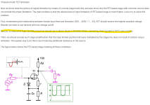
"The diode is used to emulate grid current happening on a triode when the grid voltage becomes positive."

EDIT: didn't notice the similar reply above by @lrgaraujo !
 
Last edited:
I assume different diodes will also have an effect on the FET bias, output, etc, so probably best to socket and see? You may not even notice any real difference with them omitted altogether.
 
So, actually reading the article @lrgaraujo shows that my assumption was correct. It's a tougher read simply because it appears this was translated into english, but I got the jist of what it was trying to say. The diodes are there just to limit the amount of signal hitting the JFET. I think I simply need to find a diode in my stash that has a similar forward voltage to a BAT85.

1694017213291.png
 
it would ostensibly shorten the turn off time of the jfet ... which I would expect to show up as asymmetry in the waveform ... you should be able to use any schottky ... trying to think if there's anything particularly special about the BAT85 but I've got nothing
 
The official schematic for the AMT SS-30 can be found online and there they use a BAS70 in the place of the BAT85
 
it would ostensibly shorten the turn off time of the jfet ... which I would expect to show up as asymmetry in the waveform ... you should be able to use any schottky ... trying to think if there's anything particularly special about the BAT85 but I've got nothing

From what I remember of this, there's some emphasis from the .ru and .de high gain contingent on matching the curve characteristics of the diode to the FET for a "true" tube emulation. There are a couple of extremely long threads on FSB about it.
 
ok but schottky diodes have a pretty consistent forward voltage ... like within 10s of millivolts of each other. I can't imagine their curves to be drastically different. I am surprised the high gain crowd is into this ... it must fix some of the mushiness as well, which is the problem trying to emulate high gain tube amps with jfets because the amp world's cathode bypass cap tone shaping and inter-stage signal shunting aren't 100% translated over from valves.
 
Back
Top