how to check an OP-Amp? SMD component?

kjs

New member
Hi.
Is there a way of checking if an integrated circut is ok?
I not sure what It called but, OP-AMP? SMD component?
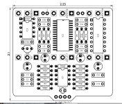
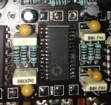
Its IC2 on the schema and called: SPIN FV-1 on the instructions.

It was hard soldering and I think I didnt get It right.
The pedal wont work and wonder if there a way of checking It and is It better check It
before or after I remove It.

the pedal is Defelctor Reverb.
 

Attachments

  • Untitled copy.jpg
    Untitled copy.jpg
    162.9 KB · Views: 12
  • Like
Reactions: fig
Here´s pic of It, I will try to remove It. If I zoom in I can see that the solder went bad.

But most interested if there is a way to check this cind of piece, if It is ok, little worried I might broke It when soldering It ( or It will break trying to remove It )

Any suggestions on how to remove It?
 

Attachments

  • IMG_6083_Fotor.jpg
    IMG_6083_Fotor.jpg
    293 KB · Views: 35
It looks like you might have a bridge between the two pins. Why do you think you broke it? What is the pedal doing or not doing. Again pictures of the front and back of the board along all connections is helpful in understanding what’s going on or not going on.
 
  • Like
Reactions: fig
I’m not knowledgeable enough on FV-1 to answer your original question, but I agree with carlinb17’s comments. More pics and info would help. Is it passing sound when by-passed on the foot switch? Are the knobs doing anything? Etc.

I’d also check the solder joints. Looks like R5 joint may need to be reflowed. That may not solve your issue, but worth checking over all the joints with good lighting and magnification.

Personally, attempting to remove an FV-1 would be one of my last resorts. Mostly because it’s the hardest (for me) to do.

Edit: I think it may be R3 instead if R5.
 
  • Like
Reactions: fig
Thanks. Will try to take more pic..
Is It important to get the joints so they are filled up on both sides of the board, Its not enough if they seems ok on the other side ( were you dont see the components ) ?

I get only dry signal now, both with or without foot switch engaged.

The led doesn't light up either.
 
  • Thinking
Reactions: fig
It works now! I clean up the joints on FV1 were It connected two legs. And cleaned up some other joints that may
had gone over to another.. I don´t know what did It but now It works.

I don't think I reflow any joints now when It works, Can I reflow them from the side of the board without the components ( the one with the pins )


The led does´t light but I can live with that or I order one extra next time ( will keep building, this was fun, this was my first build )

Thanks for the help everyone : )
Glad it works and congrats on your first build!

For the LED, check the polarity to make sure you don’t have it backwards. Could also check the value and solder joints for R102. Also make sure the LED leads aren’t grounding to the enclosure. 0B0DF299-4A93-4C8A-A366-217FD35BC7D8.jpeg
 
Honestly, if the audio is working I wouldn't reflow any of those joints. more chance of doing harm than good. I would work at getting the LED working though
 
Back
Top